
Multi-valve damper for controlling airflow and method for controlling airflow

a multi-valve, damper technology, applied in the direction of ventilation systems, heating types, domestic cooling apparatus, etc., can solve the problems of unintended airflow, and achieve the effect of minimizing the disruption of airflow

Active Publication Date: 2006-01-31
GEORGE
View PDF20 Cites 25 Cited by
  • Summary
  • Abstract
  • Description
  • Claims
  • Application Information

AI Technical Summary

Benefits of technology

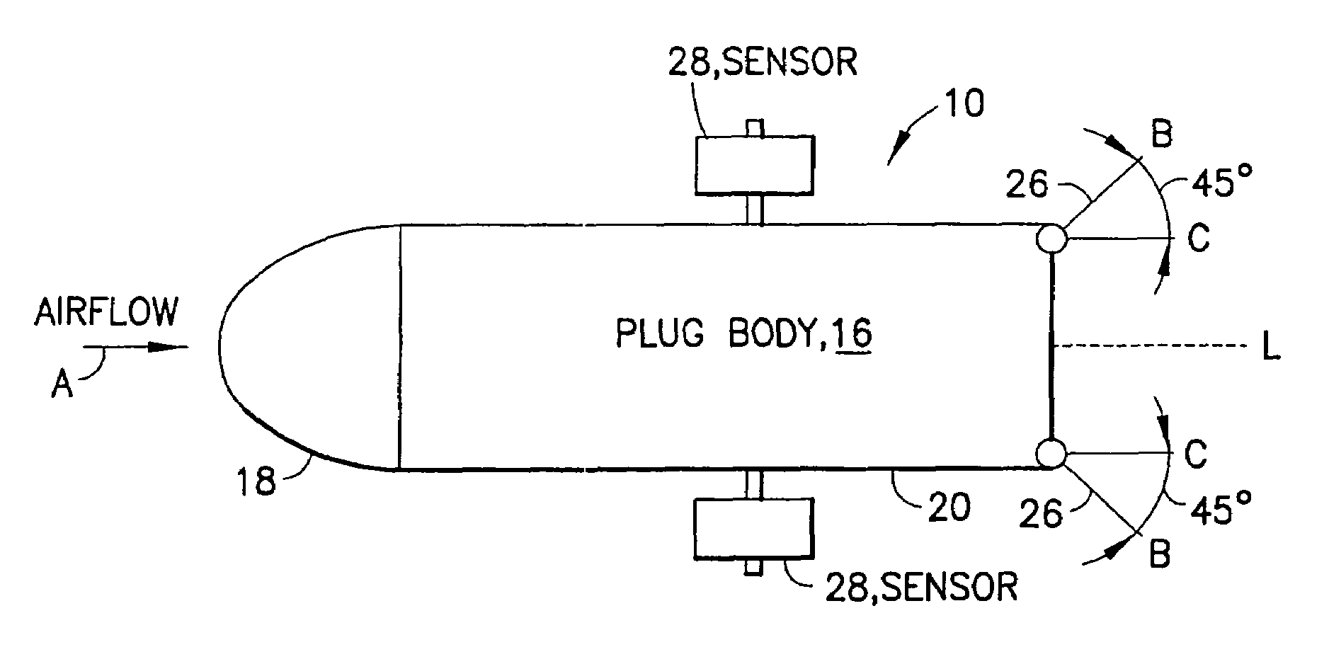
[0020]The proximal end of the plug body may have an aerodynamic shape that minimizes the disruption of airflow into the airflow sections. The distal end of the plug body may have a substantially flat shape.

Problems solved by technology

However, the airflow sections may also be unequal, depending on the application and level of airflow control desired.

Method used


Image

  • Multi-valve damper for controlling airflow and method for controlling airflow
  • Multi-valve damper for controlling airflow and method for controlling airflow
  • Multi-valve damper for controlling airflow and method for controlling airflow

Examples


Embodiment Construction

[0035]The ensuing detailed description provides exemplary embodiments only, and is not intended to limit the scope, applicability, or configuration of the invention. Rather, the ensuing detailed description of the exemplary embodiments will provide those skilled in the art with an enabling description for implementing an embodiment of the invention. It should be understood that various changes may be made in the function and arrangement of elements without departing from the spirit and scope of the invention as set forth in the appended claims.

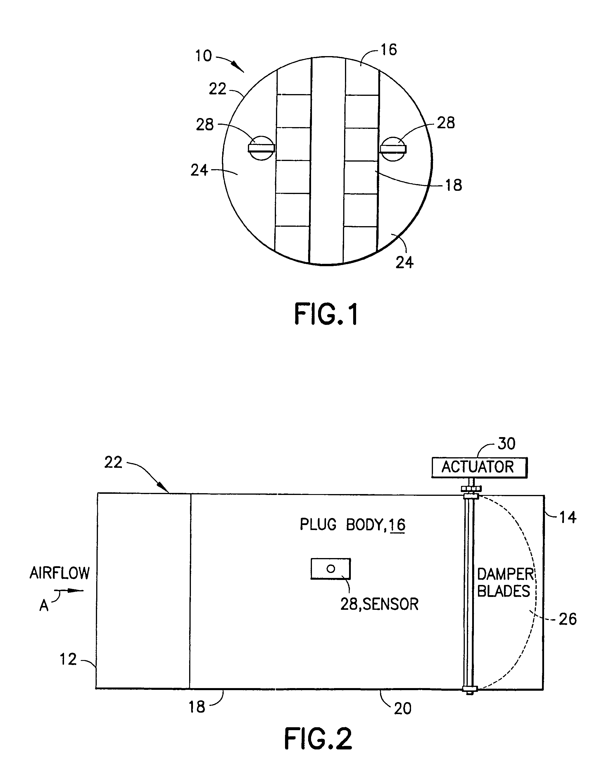
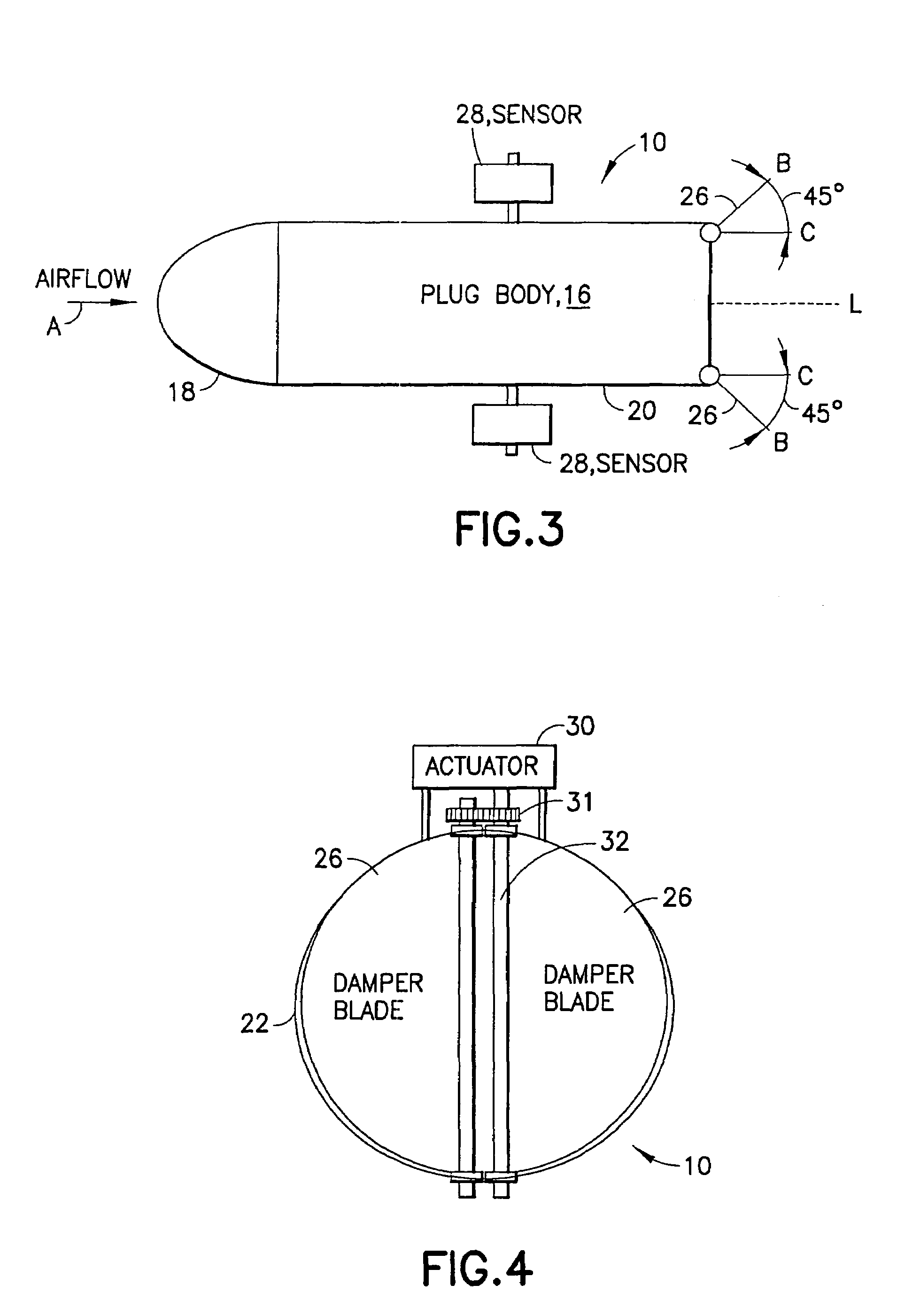
[0036]In an example embodiment of the present invention as shown in FIGS. 1–4, a multi-valve damper for an airflow duct is provided. As shown in FIG. 2, the airflow duct may have inlet section 12 and an outlet section 14, the size of which may vary depending on the airflow requirements of the application. The damper has a plug body 16 having a proximal end 18 and a distal end 20. The plug body 16 is adapted to fit within an airflow duct and to...


PUM


Abstract

The present invention relates to a multi-valve damper which divides a section of an airflow duct into at least two airflow sections. The damper has a plug body having a proximal end and a distal end. The plug body is adapted to separate a section of an airflow duct into at least two airflow sections. At least two damper blades may be mounted on the distal end of the plug body, each of the damper blades controlling airflow in a respective airflow section. At least one airflow sensor may be provided in each of the airflow sections for controlling the respective damper blades. An actuator mechanism responsive to the sensors may be provided for opening and closing the damper blades.

Description

BACKGROUND OF THE INVENTION[0001]The present invention relates to an airflow damper for controlling the flow of air in a ventilation system. In particular, the present invention relates to a multi-valve damper which divides a section of an airflow duct into at least two airflow sections, with a damper blade or valve provided for controlling the airflow in each of the airflow sections in response to sensors in each section. The present invention also provides corresponding methods for controlling airflow in a ventilation system.[0002]Air delivery and distribution systems are used for heating, ventilation, and cooling requirements in residential and commercial structures. These systems typically consist of a variety of types and sizes of airflow ducts used to direct air to or from various locations. It is desirable in such airflow systems to be able to accurately control and regulate the airflow in the ductwork. Airflow control and regulation is typically carried out by an adjustable ...

Claims


Application Information

Patent Timeline
Patent Type & Authority Patents(United States)
IPC IPC(8): F24F7/00F25D17/04F24F13/14
CPCF24F13/1413F24F2011/0038F24F2110/30Y10T137/0525Y10T137/87531
Inventor GEORGE
Owner GEORGE
Learn More