Liquid applicator with a mechanism for fracturing multiple ampoules

a liquid applicator and ampoules technology, applied in the field of hand-held liquid applicators, can solve the problems of user using both hands, difficulty in fracturing more than one ampoules, and many problems of applicators

Active Publication Date: 2006-01-31
CAREFUSION 2200 INC
View PDF17 Cites 82 Cited by
  • Summary
  • Abstract
  • Description
  • Claims
  • Application Information

AI Technical Summary

Benefits of technology

[0009]Accordingly, in one of its aspects, the present invention provides an improved hand-held liquid applicator of quality construction having a body with a mechanism that may be depressed to fracture more than one ampoule enclosed therein substantially simultaneously, releasing the liquid contained in the ampoules so that the liquid may be applied by the porous element attached to the body of the applicator.

Problems solved by technology

Numerous problems are encountered with applicators of this type.
For example, it is difficult to fracture more than one ampoule in this manner and may require a user employ both hands to break the ampoules dispensing the fluid.
Furthermore, because so much effort is required to fracture more than one ampoule, it may be difficult for the user to fracture more than one ampoule at the same time.
Furthermore, breaking ampoules one at a time is inefficient and is not reliable.

Method used


Image

  • Liquid applicator with a mechanism for fracturing multiple ampoules
  • Liquid applicator with a mechanism for fracturing multiple ampoules
  • Liquid applicator with a mechanism for fracturing multiple ampoules

Examples


example 1

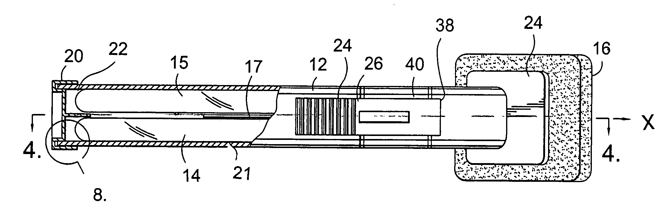
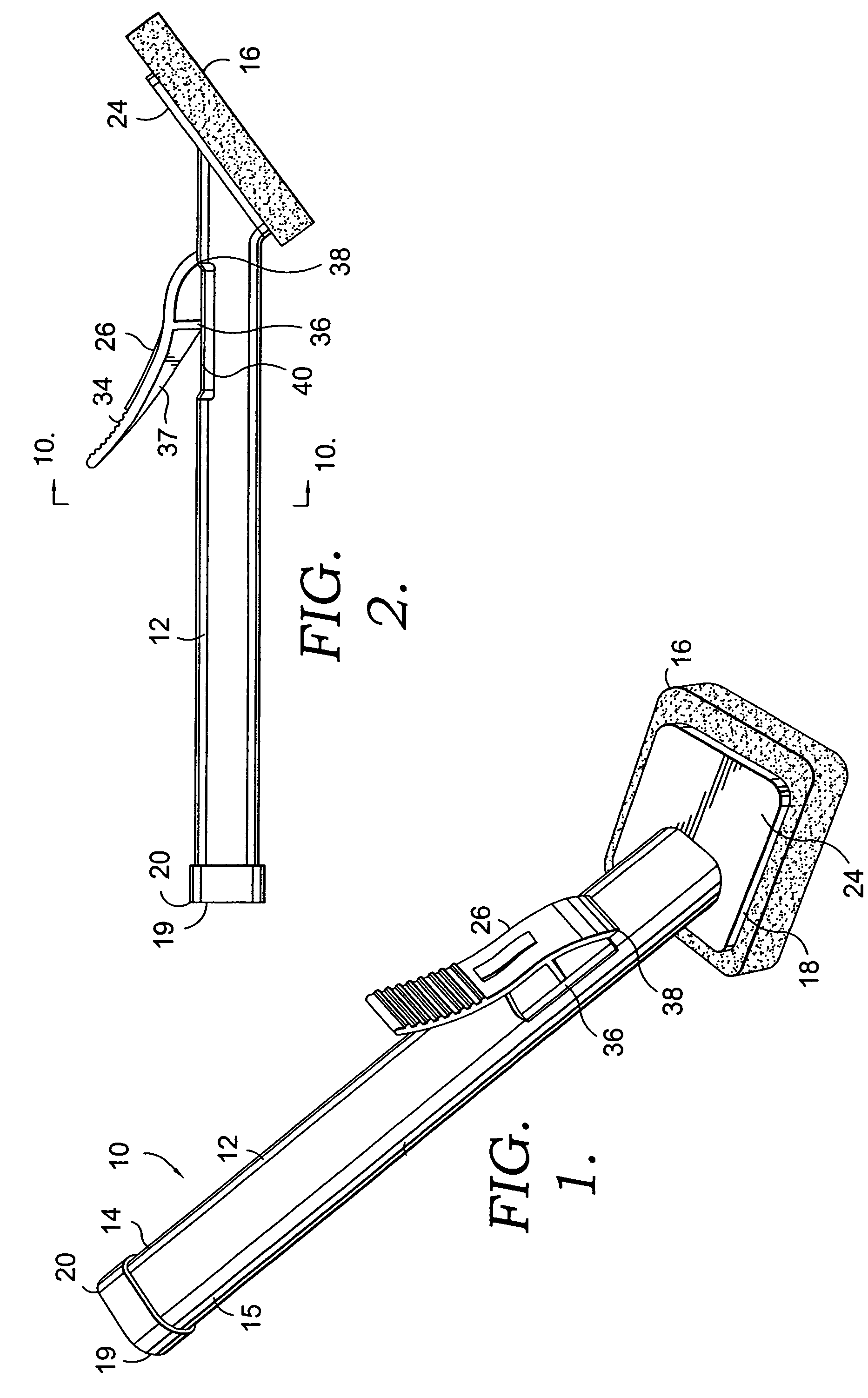
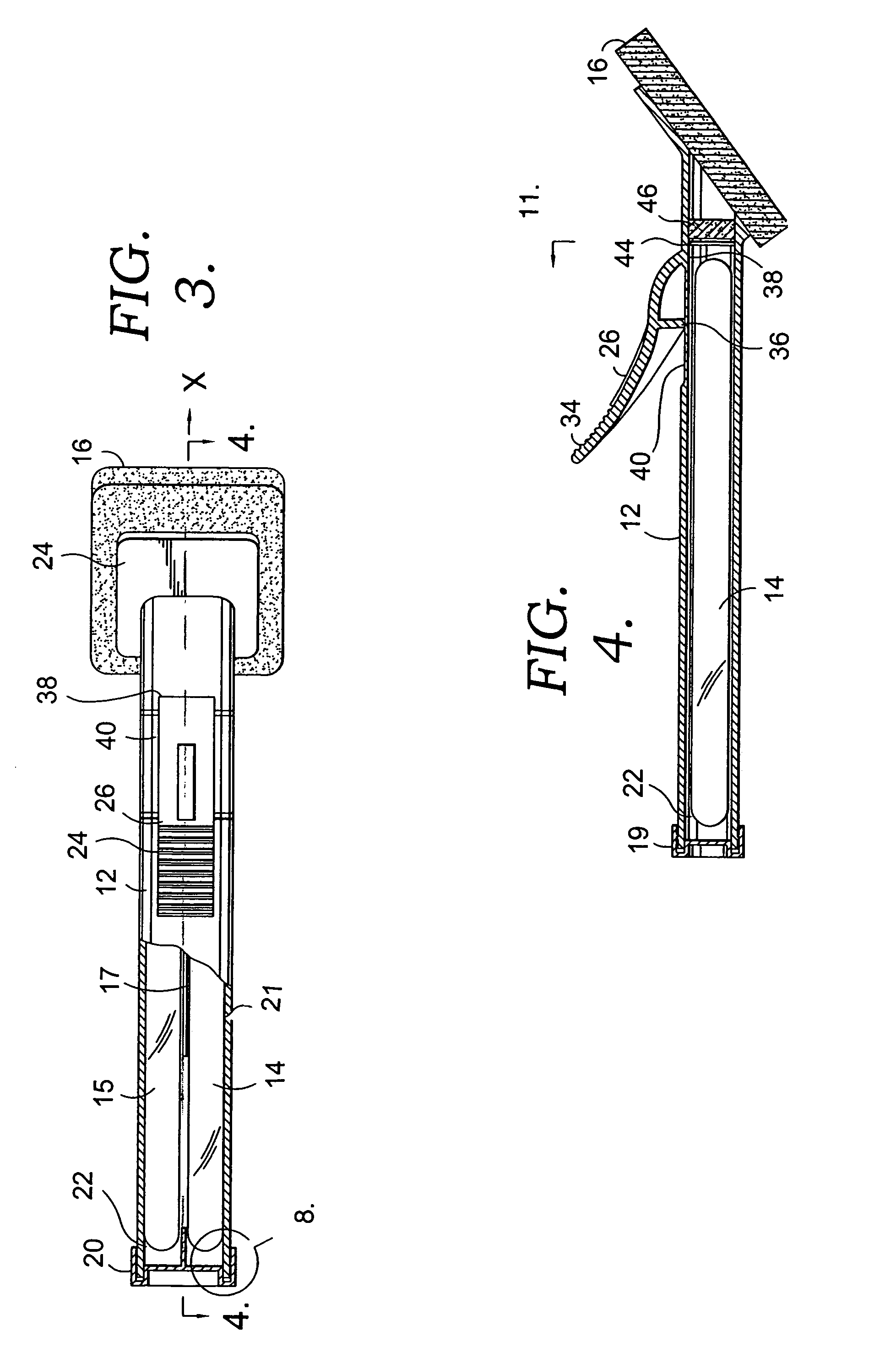
[0024]With reference FIG. 1, FIG. 2 and FIG. 3 in particular, where like reference numerals identify like elements in the various views, an embodiment of the liquid applicator is illustrated and designated generally by the numeral 10. Liquid applicator 10 generally includes a body 12, and a porous element 16 secured to flange 24 of body 12 and a lever 26.

[0025]Two ampoules 14 and 15 are received in body 12. Ampoules 14 and 15 may be used for containing various liquids such as medicaments, cleansing agents, cosmetics, polishes or the like. In the illustrated embodiment, ampoules 14 and 15 contain antiseptic solution to be applied to a patient's skin prior to surgery. Ampoules 14 and 15 are illustrated as elongated cylinders each with a central longitudinal axis. However, it will be appreciated that the principles of the present invention also may be applied to spherical or elongated polygonal ampoules. Furthermore, it will be appreciated that the principles of the present invention m...

example 2

[0045]In this embodiment, the liquid applicator 10 is constructed to house two 13 ml ampoules. The thickness of the walls of the 13 ml ampoules is 0.3 mm. It will be understood and appreciated, however, that ampoules of various sizes with various wall widths may be utilized and such is contemplated to be within the scope of the present invention. In the illustrated embodiment, the distance between the lateral line defined by the most upwardly positioned portion of the flange and the distal end of the handling portion of the lever is approximately 3.75 inches. It will be understood and appreciated, however, that this distance will vary based upon the size of the applicator and ampoule utilized. Such variations are contemplated to be within the scope of the present invention.

example 3

[0046]During formation of the applicator, the porous element is welded to the applicator body in three steps. First, the flange of the body is pre-heated with the aid of an infrared heater that is set at a temperature ranging between 620 and 625° F. The flange and the body are held in place with a nesting fixture, and a gap between the flange and the heating element is set to 0.125″. The flange is heated for approximately fifteen seconds to achieve a temperature of approximately 150 to 160° F. Next, the porous plug is manually inserted into the applicator body while the flange area is still warm. Finally, while the pre-heated body and flange containing the porous plug are still in the nesting fixture, a porous element is centered onto the flange. The flange and the porous element are bonded together with a sonic welding machine. It will be appreciated that other suitable securing expedients could be employed in place of the ultrasonic welding operation. For example, the porous eleme...


PUM


Abstract

Liquid applicators having a flexible elongated hollow body are provided. More specifically, provided are hand-held liquid applications having a flexible elongated hollow body within which at least two liquid-filled, glass ampoules are received, and a mechanism for fracturing the ampoules to release the liquid for dispensing.

Description

CROSS-REFERENCE TO RELATED APPLICATIONS[0001]This application claims the benefit of priority to U.S. Provisional Application No. 60 / 439,197 filed on Jan. 10, 2003.STATEMENT REGARDING FEDERALLY SPONSORED RESEARCH OR DEVELOPMENT[0002]Not Applicable.FIELD OF THE INVENTION[0003]The present invention relates generally to liquid applicators. More specifically, the present invention relates to a hand-held liquid applicator having a flexible elongated hollow body within which at least two liquid-filled, glass ampoules are received, and a mechanism for fracturing the ampoules to release the liquid for dispensing.BACKGROUND OF THE INVENTION[0004]Applicators for applying liquids such as medicaments or cleansing agents are known in the prior art. Conventional applicators typically provide a generally cylindrical body construction and include only one glass ampoule retained within the body; a sponge or tip secured to the body, at least one surface of which is exposed to the ampoule; and a means ...

Claims


Application Information

Patent Timeline
Patent Type & Authority Patents(United States)
IPC IPC(8): B43K5/14B05C21/00A46B11/00A61F13/40A61MA61M35/00B43K5/00B43M11/06B65D47/10
CPCA45D34/04B05C17/002A61M35/006A61M35/003A45D2200/1018
Inventor TUFTS, SCOTT A.GUZMAN, MANUALFLORES, JESUS
Owner CAREFUSION 2200 INC
Why Eureka
Try Eureka