Dual level oil impeller for drive axle assembly

a technology of oil impeller and drive axle, which is applied in the direction of drip or splash lubrication, machine/engine, transportation and packaging, etc., can solve the problems of reducing the overall operating efficiency of the drive axle assembly, requiring a significant amount of lubricating fluid, etc., and achieves adequate lubrication and reduces the amount of fluid needed

Inactive Publication Date: 2006-01-31
ARVINMERITOR TECH
View PDF10 Cites 24 Cited by
  • Summary
  • Abstract
  • Description
  • Claims
  • Application Information

AI Technical Summary

Benefits of technology

[0007]In one disclosed embodiment, the impeller comprises a center tubular portion and a plate portion. The plate portion is an auger shaped member that is welded or similarly attached to the center tubular portion. The tubular portion is preferably press-fit onto the axle shaft. The auger shaped member comprises a disc-shape that includes at least first and second radially extending edges. The first and second edges are laterally spaced apart from each other along an external surface of the tubular member to define a fluid path. As the axle shaft rotates the impeller, fluid is drawn from the center portion of the axle housing, through the fluid path in the impeller, and into the fluid cavity of the impeller housing.
[0008]The subject invention provides a simplified method and apparatus for maintaining dual fluid levels in a drive axle assembly, which reduces the amount of fluid needed to maintain adequate lubrication. These and other features of the present invention can be best understood from the following specification and drawings, the following of which is a brief description.

Problems solved by technology

This requires a significant amount of lubricating fluid.
This can decrease the overall operating efficiency of the drive axle assembly.

Method used


Image

  • Dual level oil impeller for drive axle assembly
  • Dual level oil impeller for drive axle assembly
  • Dual level oil impeller for drive axle assembly

Examples


Embodiment Construction

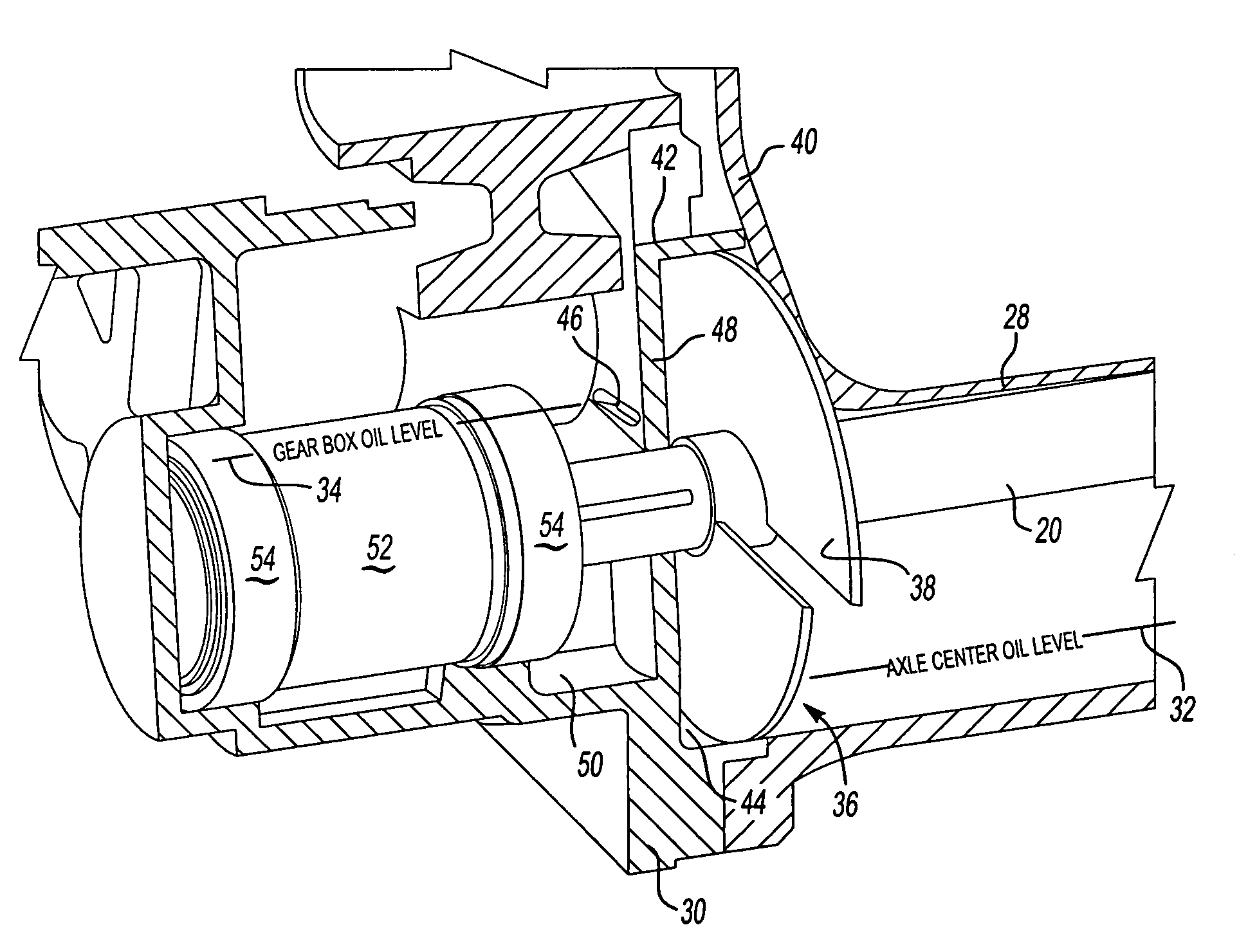
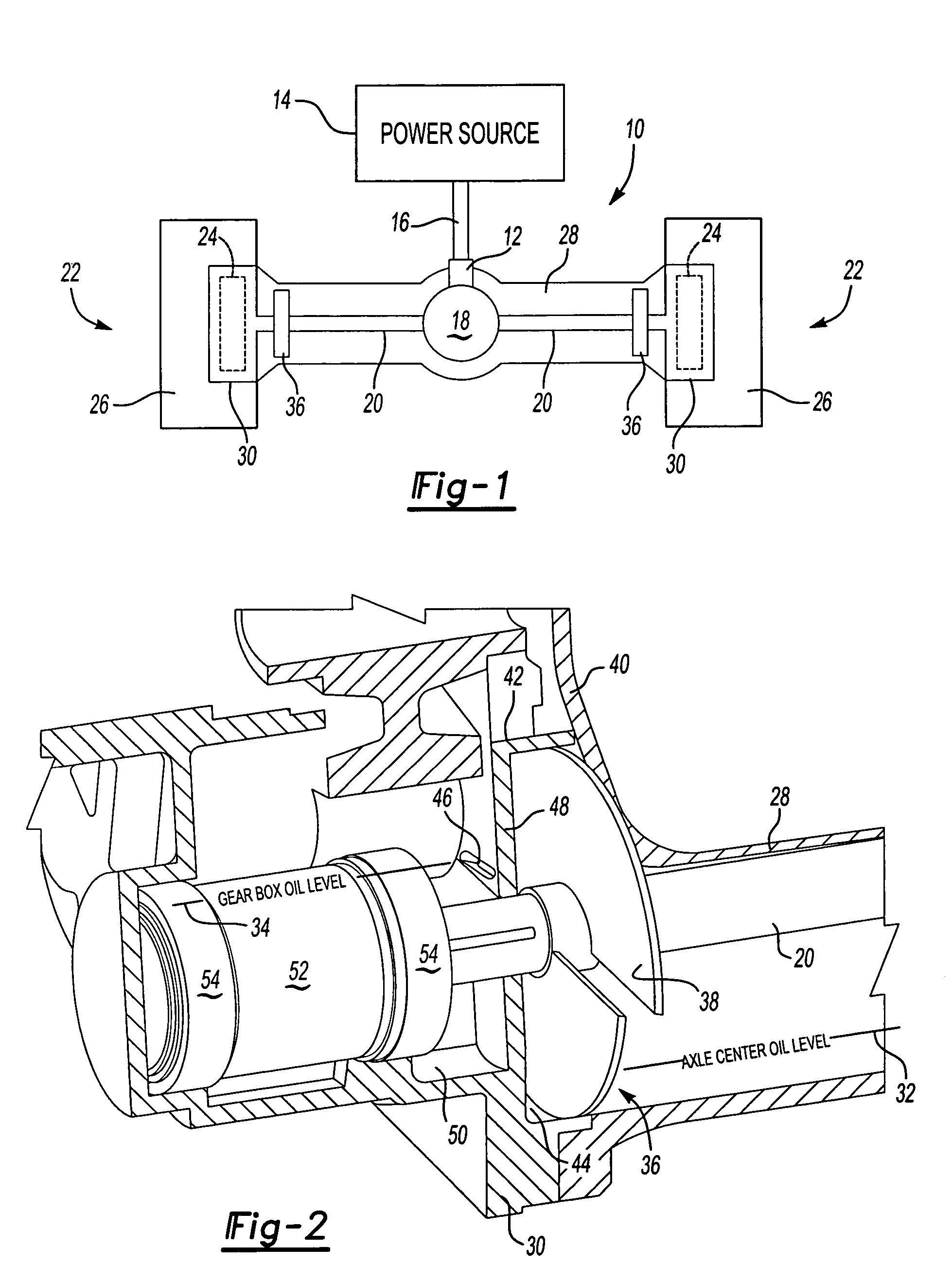
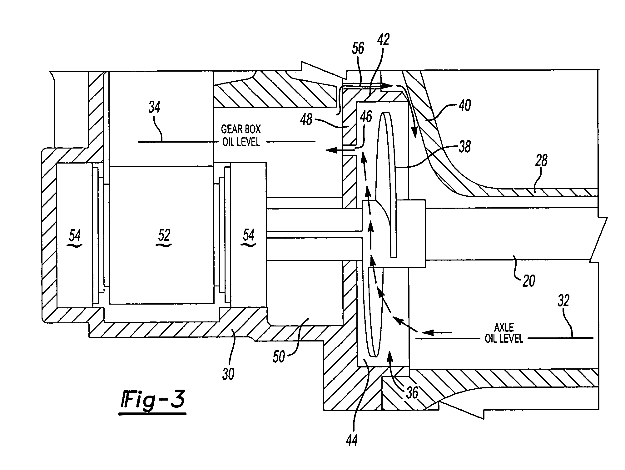
[0014]A drive axle assembly incorporating the subject invention is shown generally at 10 in FIG. 1. The drive axle assembly 10 includes an input 12 that is operably coupled to a power source 14 with a driveshaft assembly 16. The power source can be an engine, electric motor, or any other driving power source known in the art. The input 12 drives a differential assembly 18, which in turn drives a pair of axle shafts 20. The axle shafts 20 drive wheel end assemblies shown generally at 22. The differential assembly 18 is a gear set that allows speed differentiation between the axle shafts 20 as the vehicle negotiates through a turn. The operation of the differential assembly 18 is well known and will not be discussed in further detail.

[0015]The wheel end assemblies 22 each include a gear set 24 that is driven by one of the axle shafts 20, and which in turn drives a vehicle wheel 26. The gear sets 24 can be planetary, helical, or any other type of wheel end gear set known in the art. Th...


PUM


Abstract

A drive axle assembly includes an input operably coupled to a power source. The input drives first and second axle shafts, which in turn drive laterally spaced wheel ends. Each wheel end includes a gear set that is driven by one of the axle shafts. The axle shafts are enclosed within a center axle housing and the gear sets are enclosed within gear housings. The drive axle includes a pumping mechanism that maintains predetermined oil levels within the center axle housing and gear housings. The oil level in the center axle housing is lower than the oil level in the gear housing. The pumping mechanism includes an impeller that is mounted for rotation with the axle shaft. The impeller draws oil from the center axle housing into a cavity, which transfers the oil to the gear housing.

Description

BACKGROUND OF THE INVENTION[0001]The subject invention generally relates to a drive axle assembly including a pumping mechanism for maintaining a dual fluid level within the axle assembly. More specifically, the subject invention utilizes the pumping mechanism to maintain a first fluid level within an axle housing and a second, higher, fluid level within a wheel end gear housing.[0002]Many drive axle assemblies utilize gear sets at wheel ends to increase torque output. The gear sets are driven by axle shafts that receive driving input torque from a center differential gear assembly. The axle shafts and center differential gear assembly are enclosed within an axle housing and the wheel end gear sets are enclosed within gear housings mounted to opposing ends of the axle housing.[0003]In order for the center differential gear assembly and the wheel end gear sets to operate smoothly and efficiently, proper lubrication should be maintained. Traditionally, the axle assembly is filled with...

Claims


Application Information

Patent Timeline
Patent Type & Authority Patents(United States)
IPC IPC(8): F16H57/04F01M1/00B60K17/04B60K17/00B60R17/00F01M11/06F16N13/20
CPCB60R17/00F16H57/0421F16N13/20F16H57/0434Y10T74/2186Y10T74/19991
Inventor MARTIN, III, ROBERT JAMES
Owner ARVINMERITOR TECH
Why Eureka
Try Eureka