Collecting chamber for a vacuum cleaner

a vacuum cleaner and collecting chamber technology, applied in the field of collecting chambers, can solve the problems of affecting the cleaning effect, and affecting the cleaning effect, and achieve the effect of convenient disposal

Inactive Publication Date: 2006-01-31
DYSON TECH LTD
View PDF23 Cites 45 Cited by
  • Summary
  • Abstract
  • Description
  • Claims
  • Application Information

AI Technical Summary

Benefits of technology

[0007]The present invention seeks to provide a bagless vacuum cleaner in which collected dirt and dust can be conveniently disposed of.

Problems solved by technology

While bagless vacuum cleaners are successful in maintaining a consistently high level of suction, the absence of a bag can make it difficult to dispose of the dirt and dust which is collected by the cleaner.
In some cases, this can cause a fair amount of mess.
Both of these solutions have a disadvantage in that they require a user to keep a supply of spare bases or liners, which adds to the cost of maintaining the machine.

Method used


Image

  • Collecting chamber for a vacuum cleaner
  • Collecting chamber for a vacuum cleaner
  • Collecting chamber for a vacuum cleaner

Examples


Embodiment Construction

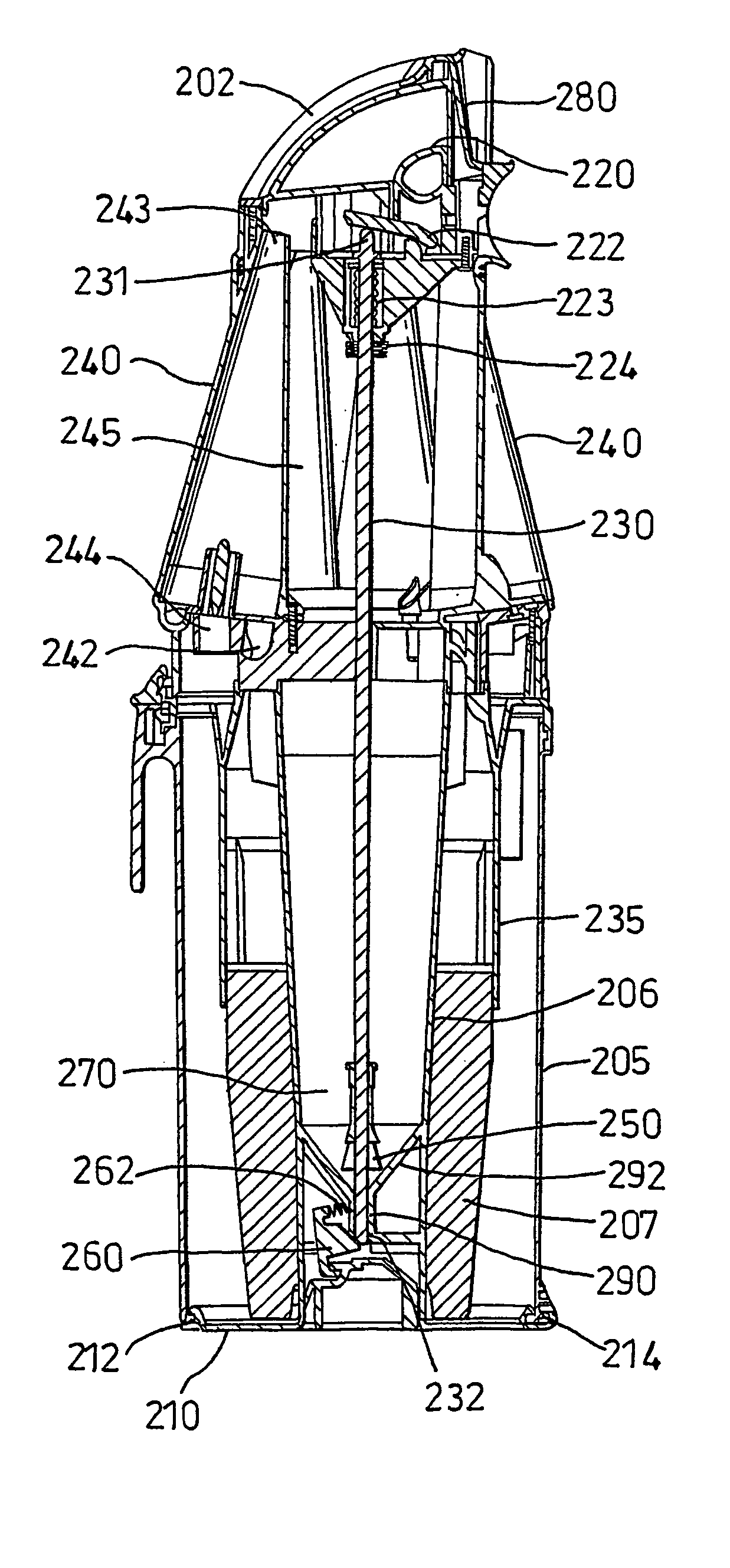
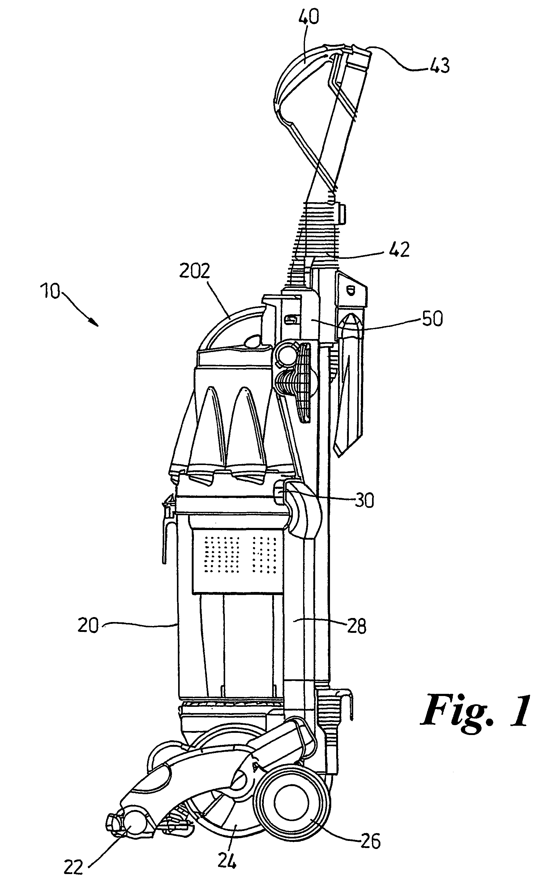
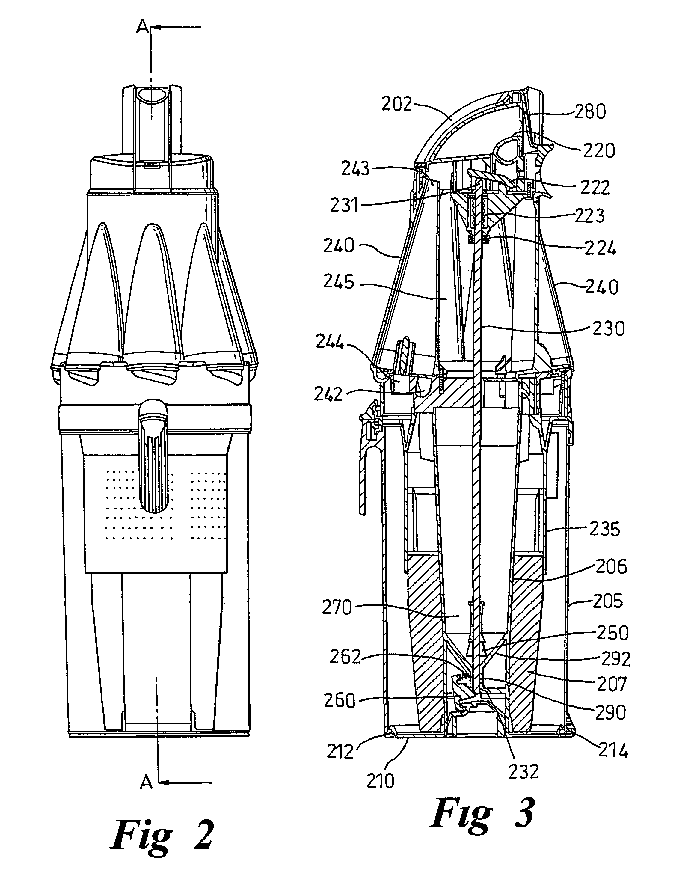
[0031]Referring to FIGS. 1 to 3, a vacuum cleaner 10 has a main chassis 50 which supports dirt and dust separation apparatus 20. The lower part of the cleaner 10 comprises a cleaner head 22 for engaging with the floor surface. The cleaner head has a downwardly facing suction inlet and a brush bar is mounted in the mouth of the inlet for agitating the floor surface. The cleaner head is pivotably mounted to a motor housing 24 which houses the motor and fan of the cleaner. Support wheels 26 are mounted to the motor housing for supporting the cleaner and allowing movement across a floor surface. A spine of the chassis 50 extends upwardly from the motor housing 24 to provide support for the components of the cleaner. A cleaning wand 42 having a second dirty air inlet 43 is connected by way of a hose (not shown) to the chassis at the base of the spine 50. The wand 42 is releasable from the spine 50 so as to allow a user to carry out above-the-floor cleaning and cleaning in places which ar...


PUM

PropertyMeasurementUnit
opening forceaaaaaaaaaa
forceaaaaaaaaaa
areaaaaaaaaaaa

Abstract

A bagless vacuum cleaner includes a separating unit for separating dirt and dust from a dirt-laden airflow which is drawn in by the cleaner. The separating unit has a chamber with a collection area for collecting dirt and dust which is separated from the airflow. A base of the separating unit is movable between a closed position and an open position. The base may be released by a trigger and a linking mechanism. The releasing mechanism is operable to apply an opening force to the base to push the base open, thereby allowing a tightly fining seal to be fitted to the base.

Description

FIELD OF THE INVENTION[0001]This invention relates to a collecting chamber for a bagless vacuum cleaner and to a vacuum cleaner which incorporates the collecting chamber.BACKGROUND OF THE INVENTION[0002]Vacuum cleaners which separate dirt and dust from an airflow without the use of a filter bag, so-called bagless vacuum cleaners, are becoming increasingly popular. Most bagless cleaners use cyclonic or centrifugal separation to spin dirt and dust from the airflow. By avoiding the use of a filter bag as the primary form of separation, it has been found possible to maintain a consistently high level of suction, even as the collecting chamber fills with dirt.[0003]The principle of cyclonic separation in domestic vacuum cleaners is described in a number of publications including EP 0 042 723. In general, an airflow in which dirt and dust is entrained enters a first cyclonic separator via a tangential inlet which causes the airflow to follow a spiral or helical path within a collection ch...

Claims


Application Information

Patent Timeline
Patent Type & Authority Patents(United States)
IPC IPC(8): B01D45/18A47L9/10A47L9/16
CPCA47L9/1625A47L9/1683A47L9/1641Y10S55/03
Inventor ORGAN, STEPHEN PAUL
Owner DYSON TECH LTD
Why Eureka
Try Eureka