Ion beam measurement systems and methods for ion implant dose and uniformity control

a technology of uniformity control and beam measurement, which is applied in the field of ion implantation systems, can solve the problems of inaccurate measurement and the inability of the dosimetry system to provide accurate beam measurements for the calibration of the implantation system, and achieve the effects of reducing beam blowup, facilitating the reduction of beam transport distance, and shortening the beam transport distan

Active Publication Date: 2006-01-31
AXCELIS TECHNOLOGIES
View PDF19 Cites 36 Cited by
  • Summary
  • Abstract
  • Description
  • Claims
  • Application Information

AI Technical Summary

Benefits of technology

[0011]The invention provides Ion beam and wafer scanning systems and methods for implanting ions from an ion beam to a treatment surface of a workpiece, wherein ions are electrically or magnetically scanned in a single direction or beam scan plane and an implanted workpiece is rotated about an axis that is at a non-zero angle relative to the beam scan plane. The workpiece rotation and the beam scanning may be synchronized to provide the beam to the workpiece treatment surface at a generally constant angle of incidence. The elimination of beam parallelizer equipment shortens the beam transport distance, thereby facilitating successful transport of low energy ion beams from the injector to the workpiece while reducing beam blowup. However, rotation of the workpiece means that the use of ordinary beam uniformity and / or dose measurement equipment would result in inaccurate measurements.
[0012]The invention also provides dosimetry systems and methods that are particularly suited for use in systems employing the above form of scanning apparatus. In such scanning systems, the scanned beam impacts the rotating wafer along a curvilinear path in a process chamber, whereby conventional dosimetry systems are unable to provide accurate beam measurements for implantation system calibration. The dosimetry systems of the invention provide for beam measurement along a curvilinear path. When used in conjunction with the scanning systems of the invention, the dosimetry system may thus advantageously take beam measurements at a number of spatial locations at which the scanned beam strikes the rotating wafer for use in adjusting of verifying implant dose and / or uniformity. The invention may thus facilitate the reduction in beam transport distance in systems having no parallelizer, without sacrificing the ability to accurately measure the beam characteristics. In addition, this invention could be used for any system where multiple degrees of freedom are required to move a faraday cup in order to measure beam flux in the surface where the ion beam is implanted into the wafer.

Problems solved by technology

However, rotation of the workpiece means that the use of ordinary beam uniformity and / or dose measurement equipment would result in inaccurate measurements.
In such scanning systems, the scanned beam impacts the rotating wafer along a curvilinear path in a process chamber, whereby conventional dosimetry systems are unable to provide accurate beam measurements for implantation system calibration.

Method used


Image

  • Ion beam measurement systems and methods for ion implant dose and uniformity control
  • Ion beam measurement systems and methods for ion implant dose and uniformity control
  • Ion beam measurement systems and methods for ion implant dose and uniformity control

Examples


Embodiment Construction

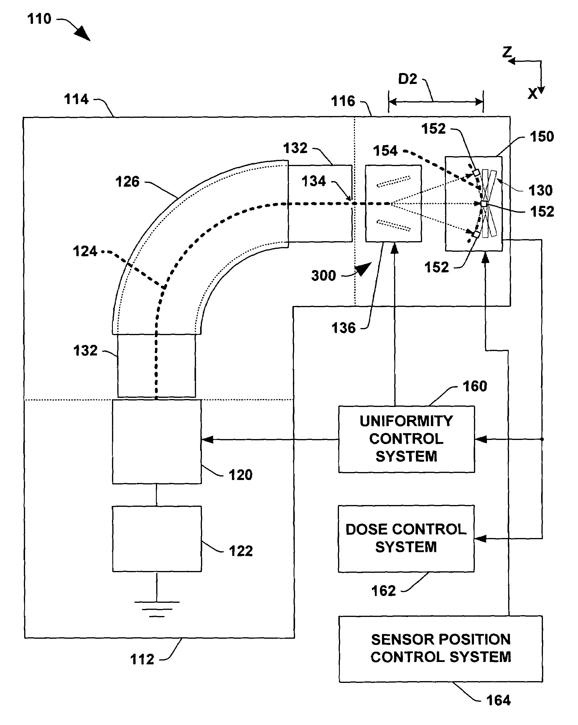
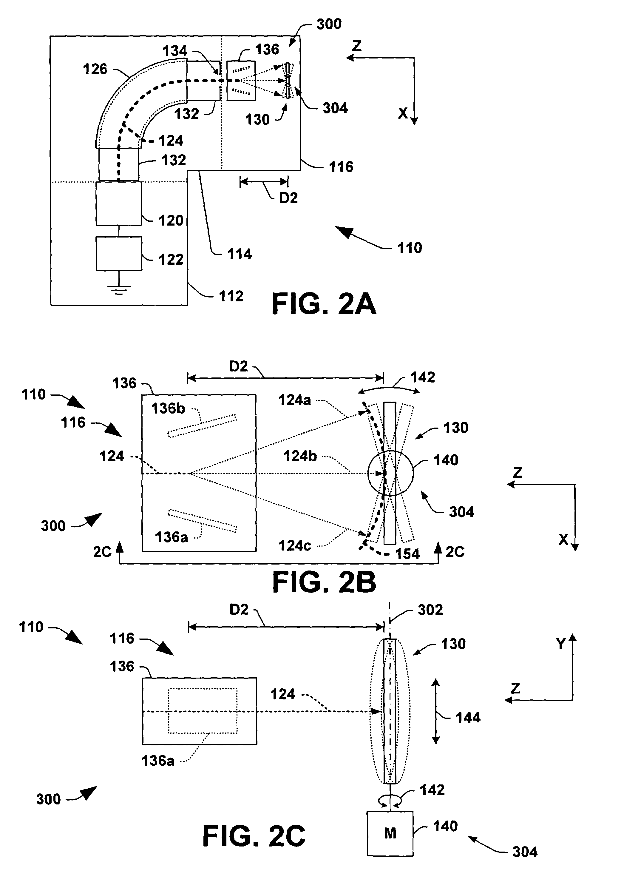
[0033]The present invention will now be described with reference to the drawings wherein like reference numerals are used to refer to like elements throughout, and wherein the illustrated structures are not necessarily drawn to scale.

[0034]Referring initially to FIGS. 2A–3F, various exemplary scanning systems 300 of the invention are hereinafter illustrated and described in which an ion beam 124 is scanned in a single beam scan plane, a semiconductor wafer or other workpiece 130 is mechanically oscillated or reciprocated back and forth about an axis 302 that is at a first angle relative to the beam scan plane, and the workpiece 130 is mechanically translated in a workpiece scan direction 144 that is at a second angle relative to the beam scan plane, wherein the mechanical oscillation is synchronized with electric or magnetic scanning of an ion beam 124. In the illustrated systems, the workpiece rotation axis 302 passes through the workpiece 130 itself, although other implementations...


PUM


Abstract

Dosimetry systems and methods are also presented for measuring a scanned ion beam at a plurality of points along a curvilinear path at a workpiece location in a process chamber. An illustrated dosimetry system comprises a sensor and a mounting apparatus that supports support the sensor and selectively positions the sensor at a plurality of points along the curvilinear path, wherein the mounting apparatus can selectively position the sensor to point toward a vertex of the scanned ion beam.

Description

RELATED APPLICATION[0001]This application is related to U.S. patent application Ser. No. 10 / 917,997, filed on Aug. 13, 2004, entitled SCANNING SYSTEMS AND METHODS FOR PROVIDING IONS FROM AN ION BEAM TO A WORKPIECE.FIELD OF THE INVENTION[0002]The present invention relates generally to ion implantation systems, and more specifically to improved systems and methods for implanting ions from an ion bean to a workpiece and for measuring ion beams in ion implantation systems.BACKGROUND OF THE INVENTION[0003]In the manufacture of semiconductor devices and other products, ion implantation is used to dope semiconductor wafers, display panels, or other workpieces with impurities. Ion implanters or ion implantation systems treat a workpiece with an ion beam, to produce n or p-type doped regions or to form passivation layers in the workpiece. When used for doping semiconductor wafers, the ion implantation system injects a selected ion species into the wafer to produce the desired extrinsic mater...

Claims


Application Information

Patent Timeline
Patent Type & Authority Patents(United States)
IPC IPC(8): H01J37/317
CPCH01J37/20H01J37/304H01J37/3171H01J2237/20207H01J2237/31703H01J2237/20235H01J2237/20242H01J2237/24528H01J2237/20214H01L21/265H01J37/317
Inventor PETRY, KLAUSFERRARA, JOSEPHBECKER, KLAUS
Owner AXCELIS TECHNOLOGIES
Why Eureka
Try Eureka