
Fluorescent lamp

Active Publication Date: 2006-01-31
SAVANT TECH LLC
View PDF11 Cites 26 Cited by
  • Summary
  • Abstract
  • Description
  • Claims
  • Application Information

AI Technical Summary

Problems solved by technology

Halophosphors, though commonly used due to their low cost, exhibit poorer color rendering properties and lower lumens compared with more expensive rare earth phosphors.
However, this lamp design has drawbacks.
The rare earth phosphor layer is very thin, and it is difficult to control its thickness.
Having two layers of phosphors also increases manufacturing difficulties, production costs, equipment usage, labor usage and production losses.
It is believed that this results in a lamp which does not fully or sufficiently utilize the available UV produced by the arc discharge.
In addition, this lamp fails to yield CRI or Ra values in the 70s, which may be desirable in some cases.

Method used


Image

  • Fluorescent lamp
  • Fluorescent lamp

Examples


example 1

[0023]A test was conducted to compare (1) a lamp of the prior art wherein the phosphor layer 16 contains the conventional rare earth trisphosphor blend, with (2) a lamp according to the present invention. The results are tabulated below.

[0024]

NominalWeight ofPhosphor WeightColorAlumina inComposition of100 hrLamp typeTemperatureBarrier LayerPhosphor LayerxyRalumens / WF32T8 SP414100 K.400 mg0.63 g YEO0.3810.3828282.8lamp of the0.39 g LAPprior art0.14 g SECAF32T8 SP414100 K.400 mg0.39 g Halo0.3810.3847782.5lamp with invented0.50 g YEOphosphor layer0.30 g LAP0.11 g SECA

[0025]As can be seen, when the invented phosphor formulation was used, the amount of expensive rare earth phosphors was able to be substantially reduced, the desired color chromaticity values were able to be substantially maintained, the desired luminous output was able to be maintained, while the desired Ra value in the 70s was able to be achieved. These results were surprising and unexpected.


PUM


Abstract

A mercury vapor discharge lamp having a barrier layer and a single phosphor layer. The phosphor layer comprises 10–50 weight percent halophosphors and 50–90 weight percent rare earth phosphors. The lamp has an Ra value of 70–81, more preferably 70–79, more preferably 75–79.

Description

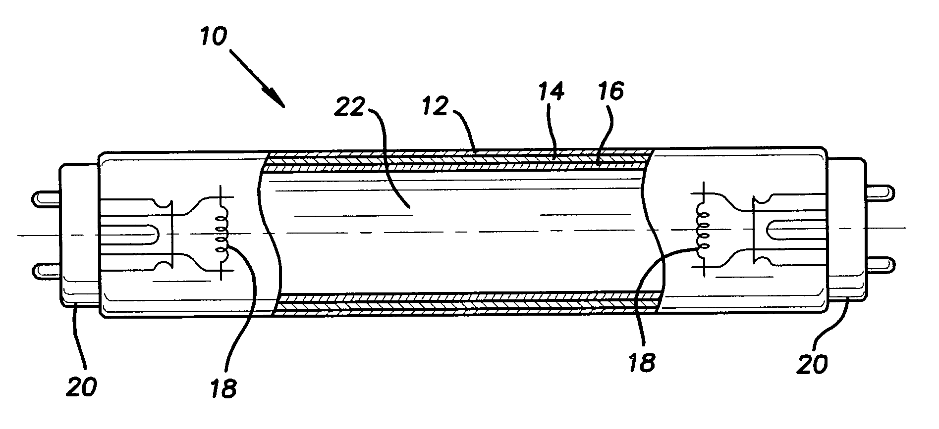
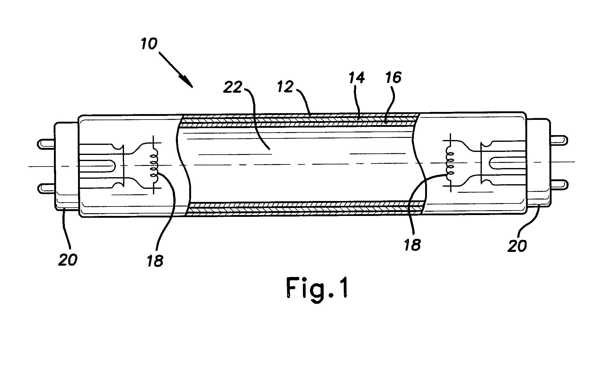
FIELD OF THE INVENTION[0001]The present invention relates generally to fluorescent lamps and more particularly to a fluorescent lamp having a barrier layer and an improved phosphor layer.DESCRIPTION OF RELATED ART[0002]There are two principal types of phosphors used in fluorescent lamps: relatively inexpensive halophosphors and relatively expensive rare earth phosphors. Halophosphors, though commonly used due to their low cost, exhibit poorer color rendering properties and lower lumens compared with more expensive rare earth phosphors. Rare earth phosphors, for example blended into a rare earth triphosphor layer as is known in the art, exhibit excellent color rendering properties and relatively high lumens.[0003]The fluorescent lighting industry provides certain medium performance lamps which have a barrier layer, preferably of alumina particles, coated onto the inside of the glass envelope, a halophosphor layer coated onto the barrier layer, and a rare earth triphosphor layer coate...

Claims


Application Information

Patent Timeline
IPC IPC(8): H01J1/62
CPCH01J61/44
Inventor JANSMA, JON B.
Owner SAVANT TECH LLC
Learn More