Test device and test module

a test device and test module technology, applied in the field of test devices, can solve problems such as increasing the cost of measuring devices

Inactive Publication Date: 2006-01-31
ADVANTEST CORP
View PDF8 Cites 8 Cited by
  • Summary
  • Abstract
  • Description
  • Claims
  • Application Information

AI Technical Summary

Benefits of technology

[0019]According to the present invention, a test device can be provided at an appropriate cost.

Problems solved by technology

This may increase the cost of the measuring device.

Method used


Image

  • Test device and test module
  • Test device and test module
  • Test device and test module

Examples


Embodiment Construction

[0030]The invention will now be described based on the preferred embodiments, which do not intend to limit the scope of the present invention, but exemplify the invention. All of the features and the combinations thereof described in the embodiment are not necessarily essential to the invention.

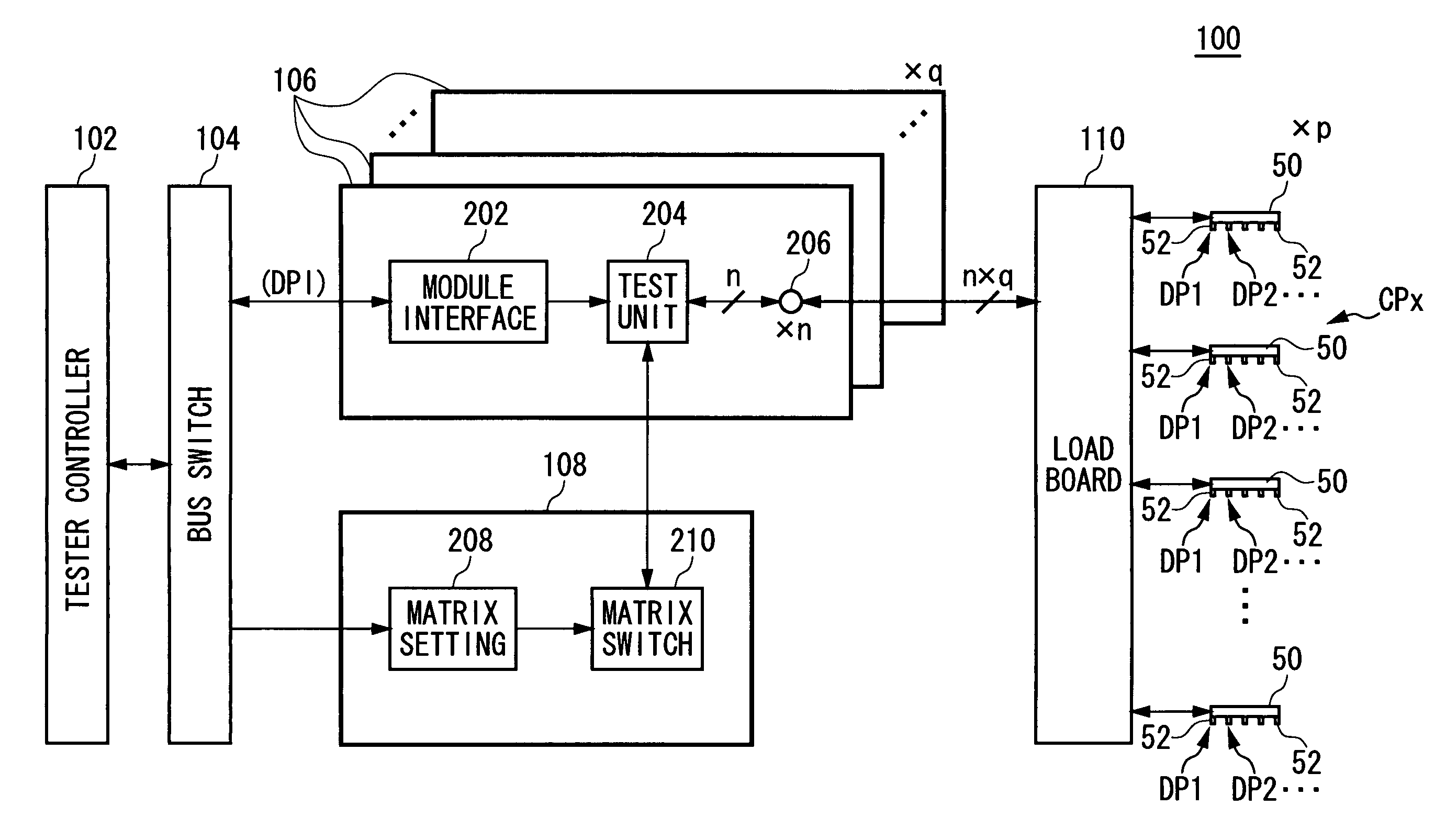
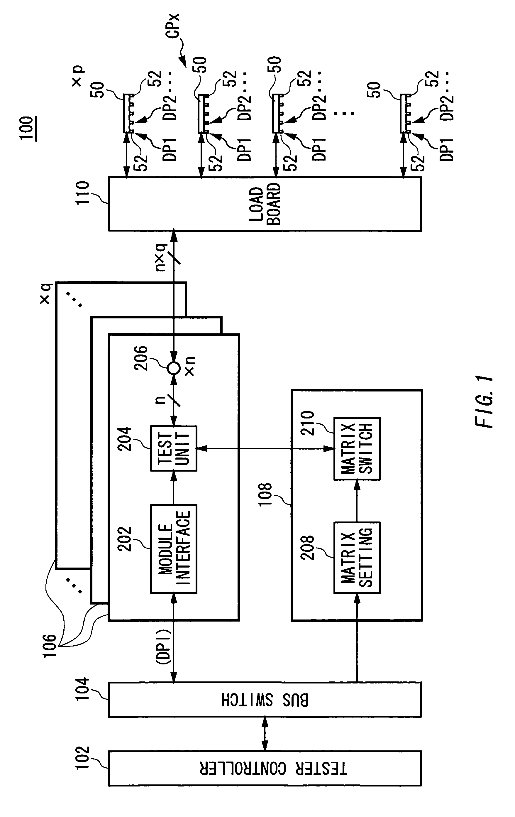
[0031]FIG. 1 illustrates an exemplary structure of a test device 100 according to an embodiment of the present invention. This example aims to provide the test device 100 that can efficiently test a plurality of electronic devices 50 as DUTs (Device Under Test) at a low cost.

[0032]The electronic device 50 of the present embodiment includes a plurality of device terminals 52. The device terminal 52 is an input and output terminal (device pin) of the electronic device 50, for example. The electronic device 50 may include a plurality of input and output interfaces having different operating frequencies or the like, for example. The test device 100 of the present embodiment aims to test these inp...


PUM


Abstract

A test device for testing an electronic device having a plurality of device terminals that receive a signal, includes: an operating condition outputting unit for outputting an operating condition indicating an operation of a signal to be supplied to a device terminal to be associated with said device terminal; and a test module for supplying a test signal used in a test of the electronic device to the electronic device based on the operation indicated by the operating condition. The test module includes: a plurality of module terminals, each of which is electrically connected to any of the device terminals, for supplying the test signal to the device terminals, respectively; a terminal correspondence storing unit for storing terminal correspondence information indicating correspondence between each device terminal and a module terminal connected to that device terminal; and an operating setting unit for selecting a module terminal connected to the device terminal associated with the operating condition based on the terminal correspondence information, and setting the operating condition for the selected module terminal.

Description

[0001]The present application is a continuation of PCT / JP2004 / 006936 filed on May 21, 2004 which claims priority from a Japanese Patent Application No. 2003-143725 filed on May 21, 2003, the contents of which are incorporated herein by reference.FIELD OF THE INVENTION[0002]The present invention relates to a test device capable of testing an electronic device having a plurality of device terminals for receiving a signal. More particularly, the present invention relates to a test device and a test module.RELATED ART[0003]In a case of simultaneously measuring a plurality of electronic devices, an arrangement is conventionally known in which given input and output terminals of a measuring device are assigned to a given electronic device as disclosed, for example, in Japanese Patent Application Publication (Laid-Open) No. 5-322978, at pages 4–6, FIGS. 1–4. In this measuring device, assignment of the input and output terminals of the measuring device is determined by using a pin definitio...

Claims


Application Information

Patent Timeline
Patent Type & Authority Patents(United States)
IPC IPC(8): G08B29/00G01R31/319
CPCG01R31/31919G01R31/31928G01R31/31926G01R31/317
Inventor WASHIZU, NOBUEI
Owner ADVANTEST CORP
Why Eureka
Try Eureka