Ultra-high pressure circuit monitoring system for solar power generation

A technology for monitoring systems and high-voltage lines, applied in the direction of measuring electricity, measuring devices, and measuring electrical variables, etc., can solve problems such as failure to monitor changes in faults, high cost and difficulty in manufacturing, and prevent problems before they happen, so as to reduce equipment complexity and Fault points, improved fault location and accidents, and flexible configuration effects

Inactive Publication Date: 2011-04-27
SOUTHEAST UNIV +2
View PDF2 Cites 2 Cited by
  • Summary
  • Abstract
  • Description
  • Claims
  • Application Information

AI Technical Summary

Problems solved by technology

Most of them are powered by batteries. In this way, the detection device only detects and processes specific sudden fault signals, and is in a dormant state to save power. The fatal disadvantage of this method is serious false positives and false negatives. , it is impossible to monitor the gradual fault changes, and it can only be reported after the fault bursts, and it is impossible to prevent problems before they happen through long-term monitoring of parameter changes, especially for icing, which needs to be accumulated for a long time Evolving faults, the above methods cannot be detected at all
[0005] Another kind of method that has a small amount of reports but has not been put into practical use is the monitoring device installed on the transmission line tower, which uses solar energy for power supply, but the parameters monitored are mainly meteorological parameters such as temperature, humidity and wind speed near the transmission line and the pole tower. Peripheral conditions such as inclination and shaking cannot detect faults such as short circuit, open circuit, grounding, overload, etc. of the transmission line, and cannot meet the requirements for monitoring the operating parameters and faults of the transmission line concerned by the power system, and have little practical significance
[0006] Under the above conditions, in order to detect these transmission line faults, it is necessary to use sensors with high dielectric strength to ensure the isolation between high and low voltage; as the voltage level of transmission lines continues to increase, high dielectric strength must use huge structures And complex process to achieve, directly resulting in high cost and manufacturing difficulty
No matter which of the above-mentioned power supply methods is adopted, the high-voltage line monitoring device cannot conduct long-term monitoring of direct operating state parameters such as load current and conductor temperature of high-voltage and ultra-high-voltage transmission lines and on-site environmental parameters, which is not conducive to timely reflection of the state of high-voltage lines trend, with great limitations

Method used


Image

  • Ultra-high pressure circuit monitoring system for solar power generation
  • Ultra-high pressure circuit monitoring system for solar power generation
  • Ultra-high pressure circuit monitoring system for solar power generation

Examples


Embodiment Construction

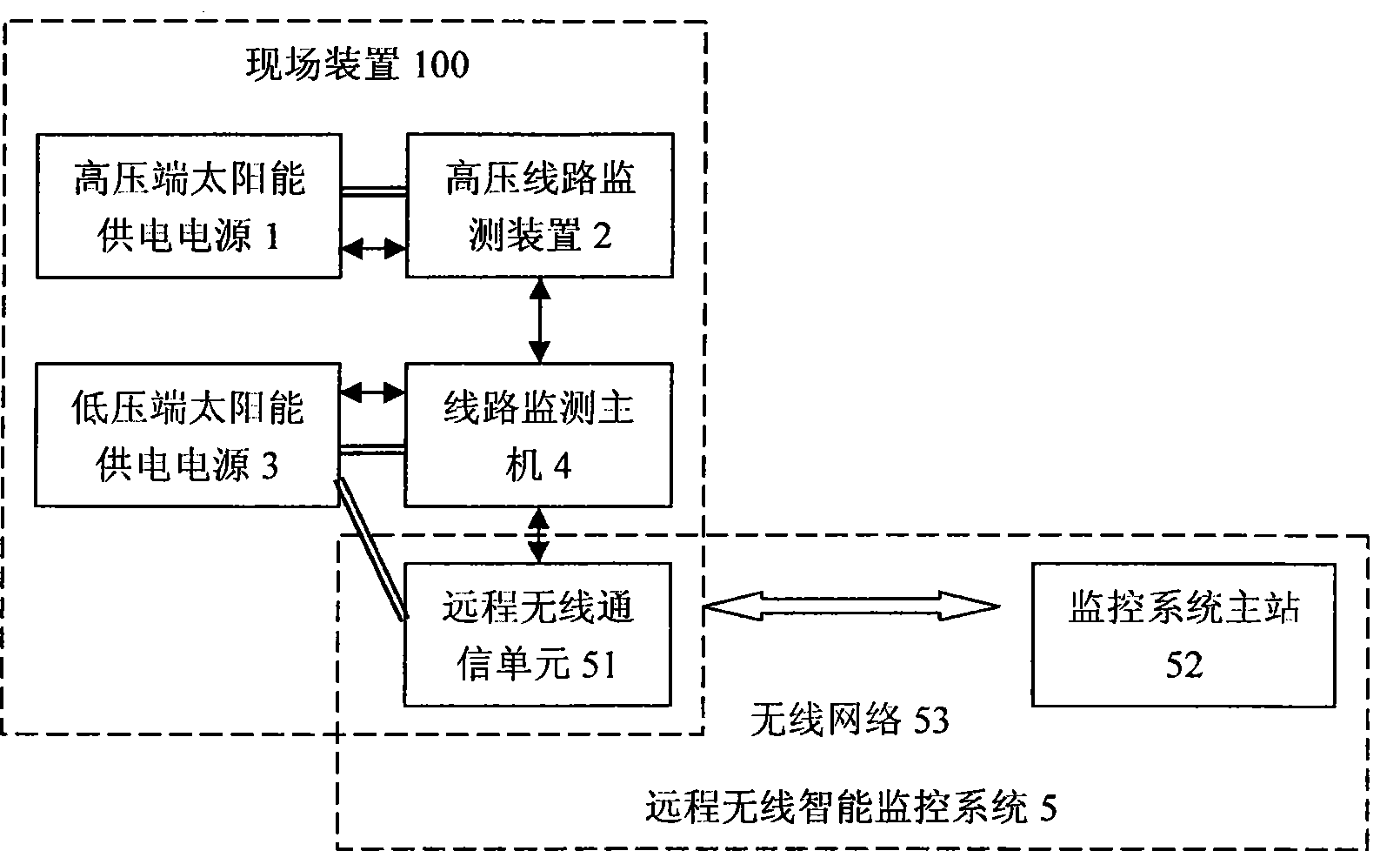
[0041] Such as figure 1 As shown, the high-voltage side solar power supply 1, the high-voltage line monitoring device 2, the low-voltage side solar power supply 3, the line monitoring host 4, and the remote wireless communication unit 51 in the remote wireless intelligent monitoring system 5 constitute the field device 100 to realize high-voltage and ultra-high voltage Online monitoring of the line; the monitoring system master 52 of the remote wireless intelligent monitoring system 5 serves as the remote part of the present invention and provides a user application interface.

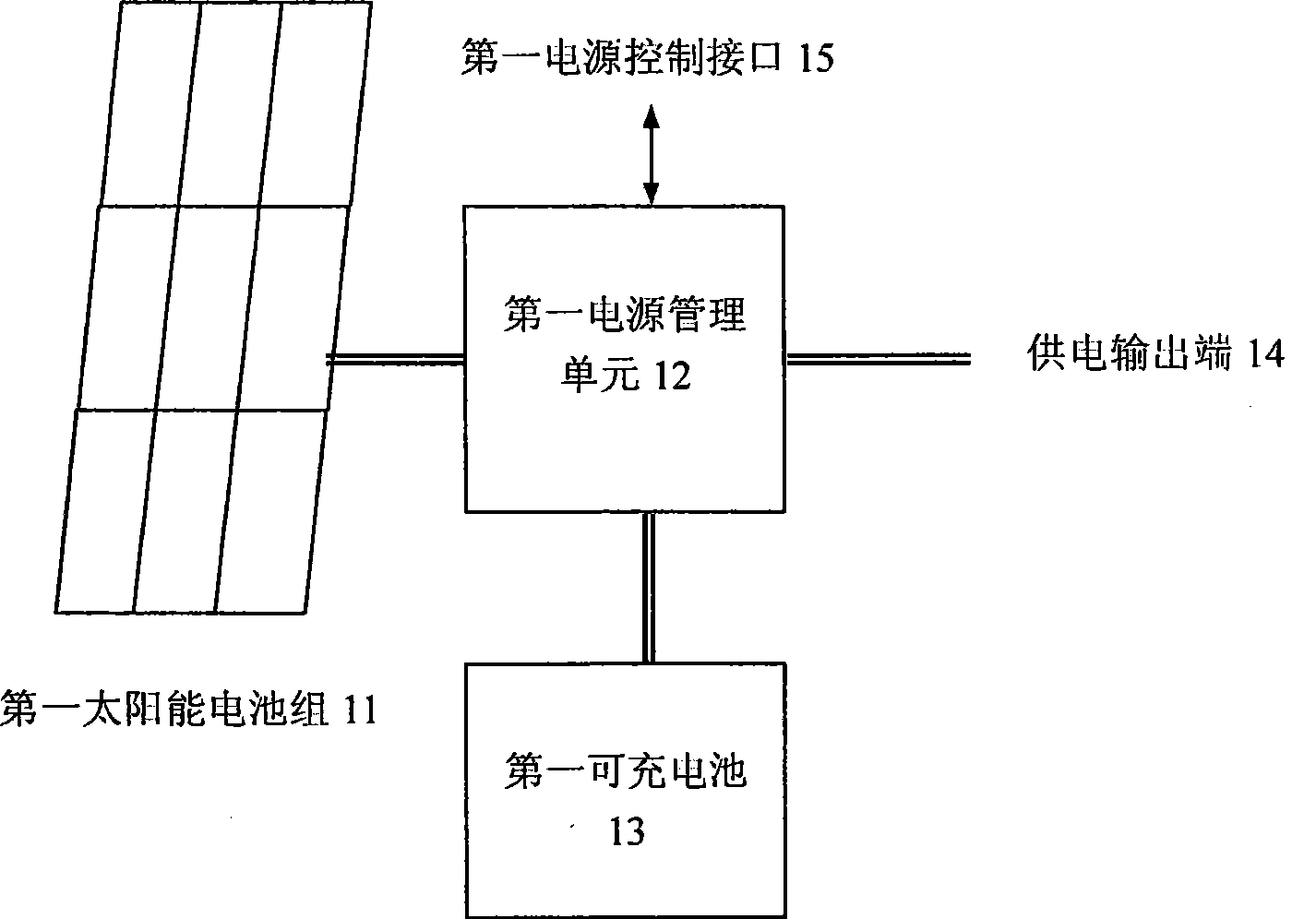
[0042] The power supply output end 14 of the high-voltage side solar power supply 1 is connected to the high-voltage line monitoring device 2 to provide working energy.

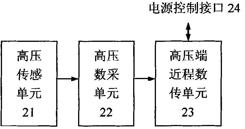
[0043] The high-voltage line monitoring device 2 is connected to the first power control interface 15 of the high-voltage side solar power supply 1 through the power control interface 24 to obtain its working status and control its working ...


PUM


Abstract

The invention relates to a solar-powered ultra-high voltage line monitoring system, comprising a high-voltage side solar power supply, a high voltage line monitoring device, a low-voltage side solar power supply, a line monitoring host computer and a remote wireless intelligent monitoring system. The high-voltage side solar power supply and the low-voltage side solar power supply comprise solar batteries, rechargeable batteries and power management units; the high voltage line monitoring device and the line monitoring host computer comprise sensing units as well as data acquisition and recording units for detecting and processing field parameters of various lines; and the remote wireless intelligent monitoring system comprises a wireless communication unit and a monitoring system master station. The high-voltage side solar power supply, the high voltage line monitoring device, the low-voltage side solar power supply, the line monitoring host computer and the remote wireless intelligent monitoring system compose a field device which collects and records the running status and fault information of high-voltage lines through solar power and transmits the running status and fault information to the monitoring system master station through the remote wireless communication unit so as to provide real-time information for power line monitoring.

Description

Technical field [0001] The invention relates to a power supply line detection system, and more specifically, to a solar power generation ultra-high voltage line monitoring system. Background technique [0002] Power lines often have short circuits, ground faults, and stolen wires. Bad weather such as strong winds, rain, snow, and freezing can also cause line failures. It is very difficult to find and locate faults. In order to improve the power supply reliability of the power grid, the power plants, substations, branch points, special transformers, distribution transformers and other key points in the power grid are equipped with equipment and devices for monitoring and protection of operating conditions. Their monitoring and control , Transmission and recording technologies are mature; however, on long-distance transmission high-voltage and ultra-high-voltage lines, only some field parameters and fault state detection have been piloted. From the perspective of implementation ef...

Claims


Application Information

Patent Timeline
Patent Type & Authority Patents(China)
IPC IPC(8): G01R31/00G01R31/08G01R31/02H04L12/28
Inventor 程明孟绍良欧阳谊明郭冰
Owner SOUTHEAST UNIV
Why Eureka
Try Eureka