
Communication device and method

a communication device and communication method technology, applied in the field of communication devices and methods, can solve problems such as excessive delay along the connection, and achieve the effect of improving the communication in the system

Inactive Publication Date: 2006-01-31
TELEFON AB LM ERICSSON (PUBL)
View PDF12 Cites 37 Cited by
  • Summary
  • Abstract
  • Description
  • Claims
  • Application Information

AI Technical Summary

Benefits of technology

[0018]In accordance with embodiments of the present invention, a sender in a communication will conduct a response procedure in response to an event that triggers a data loss detection mechanism, where the response procedure comprises at least two different modes for adapting the adaptive parameters used in flow control. In this way the method and device of the present invention are highly flexible in their management of triggering events, and can especially be implemented in such a way that the response procedure may be chosen depending on various potential causes of the triggering event, such that the correct responsive measures to a given situation may be invoked, and thereby measures can be avoided that might actually aggravate situations that may occur after a data loss detection mechanism was triggered.
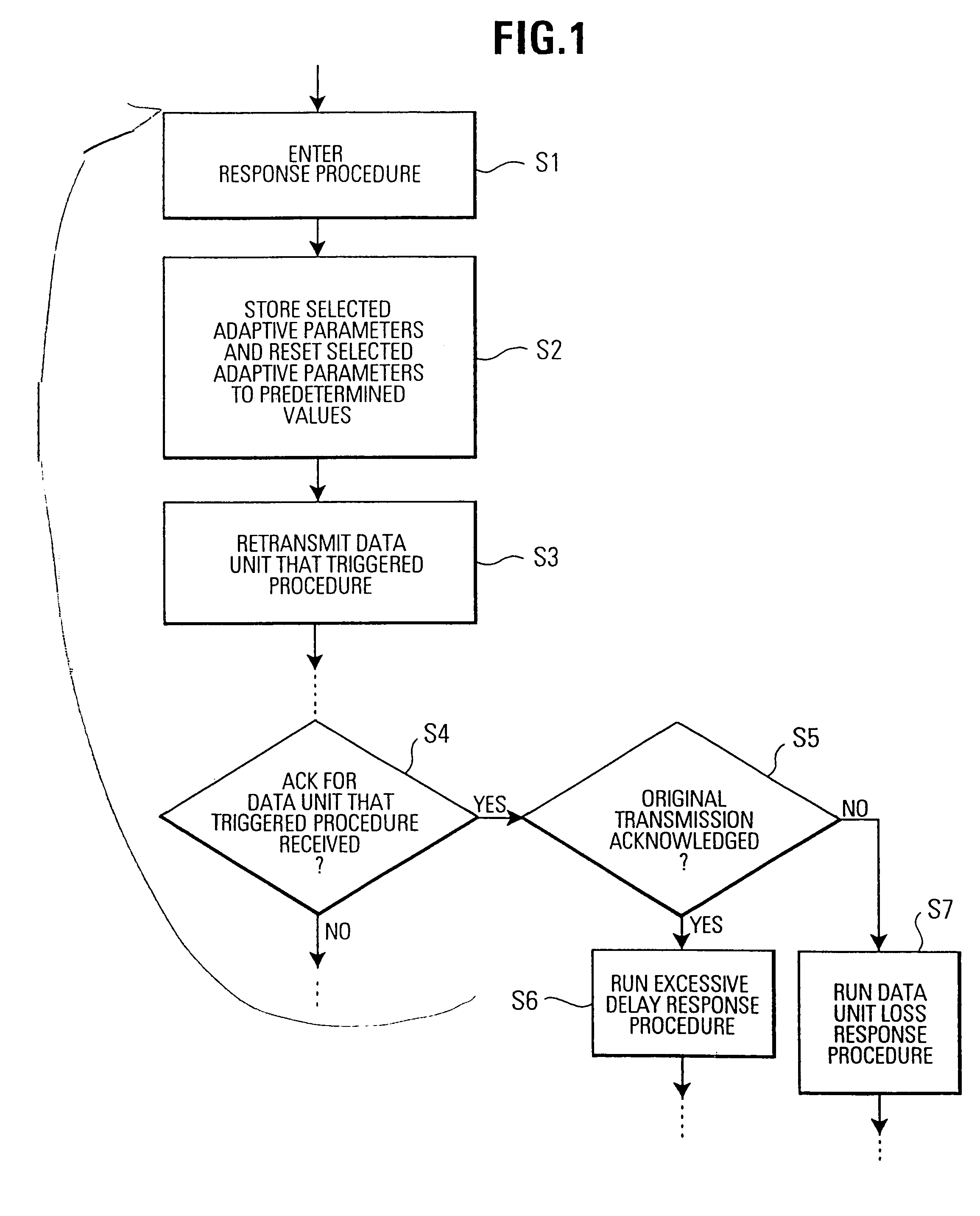
[0021]More specifically, as will also be explained in more detail in the following, the judgment that data units have been lost will be answered by reducing the transmission rate to thereby avoid further congestion. On the other hand, if there is excessive delay along the connection, then the measures taken in response to a supposed loss of data units would not be helpful, much rather they might actually aggravate the problem causing the excessive delay. Consequently, the response procedure to excessive delay will typically be different, and e.g. comprise keeping the transmission rate at the previous level, but on the other hand increasing the time-out period, such that further unnecessary retransmissions are avoided.

Problems solved by technology

More specifically, a first mode is associated with the loss of a data unit, and the second mode is associated with an excessive delay along the connection.

Method used


Image

  • Communication device and method
  • Communication device and method
  • Communication device and method

Examples


Embodiment Construction

[0029]Although the following description will be generally directed towards any communications protocol that makes use of data acknowledgment and also provides a time-out feature, examples will often be given that relate to the transmission control protocol TCP known from the TCP / IP protocol suite. The application of the present invention to this protocol is a preferred embodiment. In order to avoid any unnecessary repetition, the disclosure in the introduction of this application is incorporated into the invention disclosure.

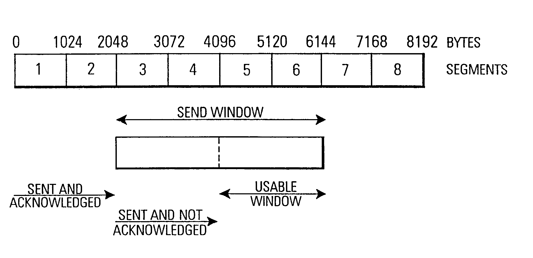
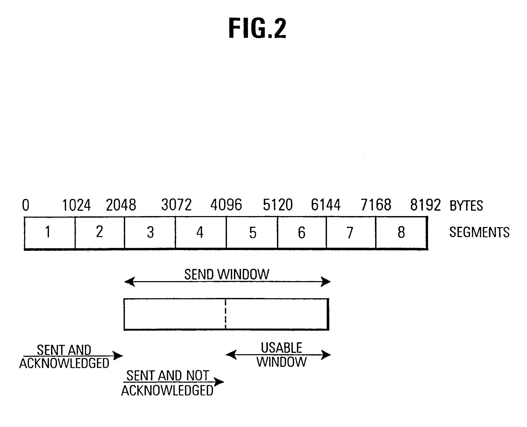
[0030]FIG. 1 shows a partial flow diagram of a preferred embodiment of the present invention. As can be seen, step S1 indicates that a response procedure is entered. FIG. 1 does not show the flow control procedure leading up to this point, as it is of no importance for the present invention. For example, it may be the window-based flow control procedure explained in connection with FIG. 2 and e.g. well known from TCP. It is only important for the invention that...


PUM


Abstract

A device and method for controlling data unit communications between a sender and a receiver, and flexibly responding to a potential data loss event. Data to be sent are divided into data units and transmitted from the sender to the receiver. The receiver acknowledges correct receipt of the data units by returning acknowledgment data units to the sender. If the receiver fails to receive a data unit, the sender retransmits the data unit using a flow control procedure using adaptive parameters and the acknowledgment data units. If the receiver then correctly receives and acknowledges the data unit, the sender determines whether the data unit was correctly received as a result of the original transmitting step or the retransmitting step. If the former (i.e., the original transmitting step), an excessive delay response procedure is selectively performed. If the latter (i.e., the retransmitting step), a data unit loss response procedure is selectively performed.

Description

BACKGROUND OF THE INVENTION[0001]The present invention relates to a communication device and method, where a data unit oriented communication between a sender and a receiver is performed, said sender and receiver operating in accordance with a predetermined communication protocol.[0002]Data unit oriented communication is well-known. In data unit oriented communication an amount of data is divided into one or more data units, where the structure of the data units is defined by a communication protocol to which the sender and receiver in the communication adhere. The protocol also defines how specific information is to be coded, and how the sender and / or receiver may react to specific information. Data unit oriented communication is also known as packet exchange communication. It should be noted that the data units used in connection with specific protocols have different names, such as packets, frames, segments etc. For the purpose of the present description, the term “data unit” sha...

Claims


Application Information

Patent Timeline
Patent Type & Authority Patents(United States)
IPC IPC(8): G01R31/00H04L1/00H04L1/16H04L1/18H04L12/70H04L29/06H04L29/08H04Q11/04
CPCH04L69/326H04L1/1628H04L1/1635H04L1/1803H04L1/1809H04L1/1835H04L1/1858H04L1/187H04L1/188H04L29/06H04Q11/0478H04L69/16H04L69/161H04L69/163H04L69/324H04L1/0001H04L2012/5647H04L2012/5649H04L1/0002H04L1/18H04L9/40
Inventor MEYER, MICHAELLUDWIG, REINER
Owner TELEFON AB LM ERICSSON (PUBL)
Learn More