Tidal seepage meter

a seepage meter and seepage technology, applied in the field of seepage meters or lee meters, can solve the problems of increasing costs and dangers for divers

Inactive Publication Date: 2006-01-31
NAVY SEC OF THE UNITED STATES
View PDF3 Cites 19 Cited by
  • Summary
  • Abstract
  • Description
  • Claims
  • Application Information

AI Technical Summary

Problems solved by technology

Typical seepage meters can only obtain one sample per use, which increases cost and danger to divers when used to obtain multiple samples over a time period.

Method used


Image

  • Tidal seepage meter
  • Tidal seepage meter
  • Tidal seepage meter

Examples


Embodiment Construction

[0011]The present invention is directed to a method and apparatus for tidal seepage meters. Although the invention is described with respect to specific embodiments, the principles of the invention, as defined by the claims appended herein, can obviously be applied beyond the specifically described embodiments of the invention described herein. Moreover, in the description of the present invention, certain details have been left out in order to not obscure the inventive aspects of the invention. The details left out are within the knowledge of a person of ordinary skill in the art.

[0012]The drawings in the present application and their accompanying detailed description are directed to merely exemplary embodiments of the invention. To maintain brevity, other embodiments of the invention that use the principles of the present invention are not specifically described in the present application and are not specifically illustrated by the present drawings.

[0013]The present inventive meth...


PUM


Abstract

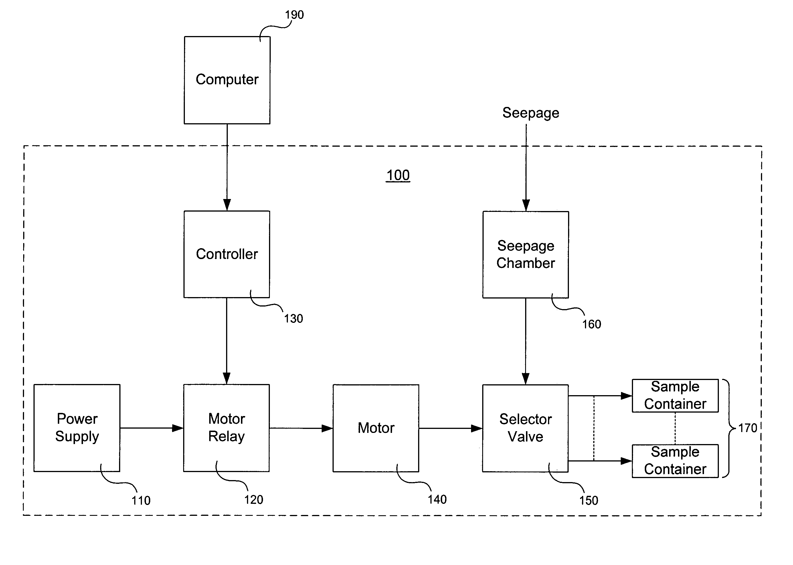
A method and apparatus for tidal seepage meters. The meter includes a power supply, controller, motor, selector valve, seepage chamber and at least two sample containers. The controller is operatively coupled to the power supply and is capable of controlling the power supply in accordance with a sampling schedule. The motor is operatively coupled to the power supply and is capable of receiving power from the power supply in accordance with the sampling schedule. The selector valve includes an input port and at least two outlet ports and is operatively coupled to the motor. The selector valve is capable of selecting an output valve in accordance with the sampling schedule. The seepage chamber is operatively coupled to the selector valve, capable of receiving seepage and inputting seepage to the selector valve via the input port. The sample containers are operatively coupled to the selector valve and receive seepage.

Description

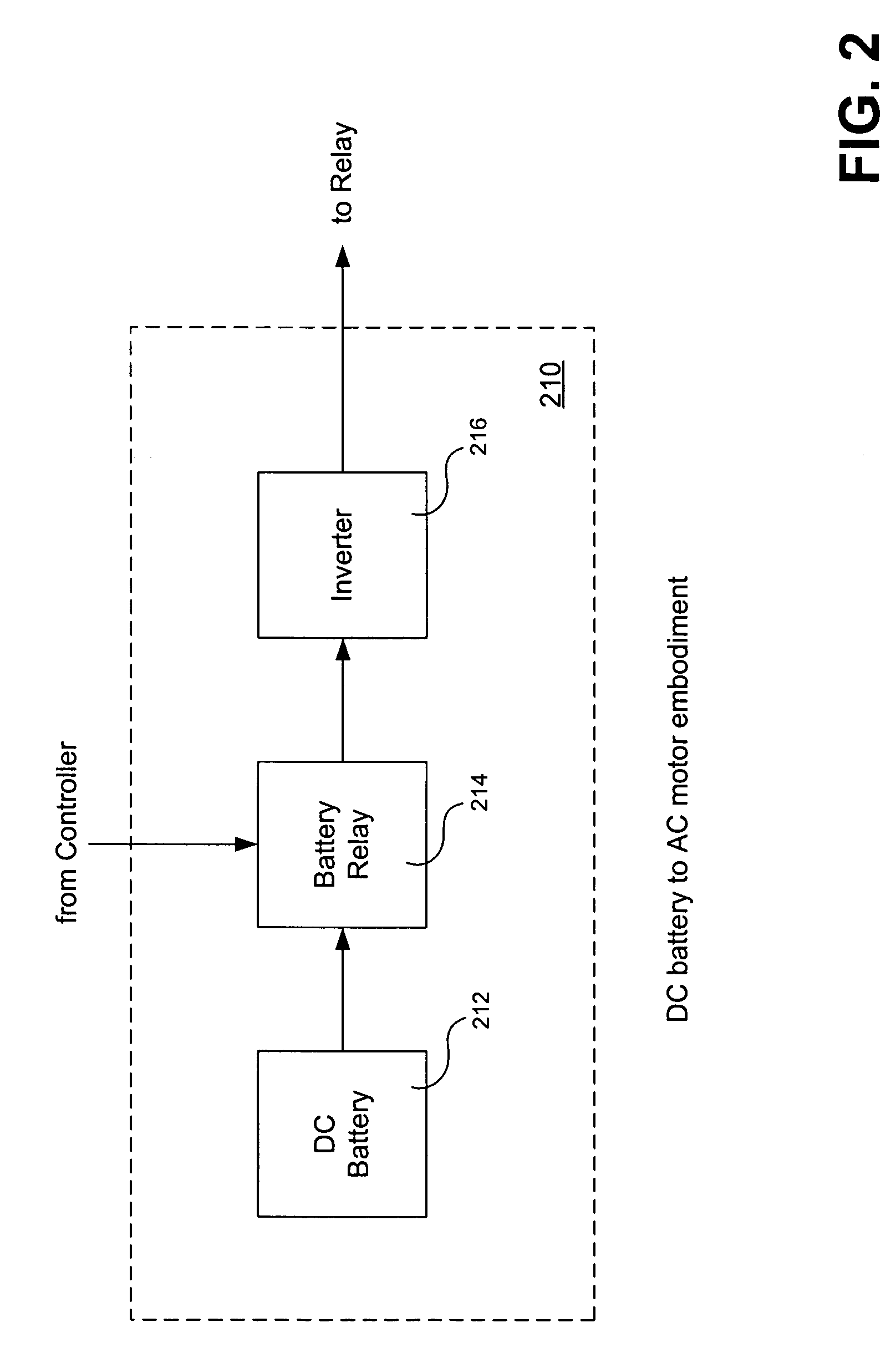
BACKGROUND OF THE INVENTION[0001]The present invention is generally in the field of seepage meters or Lee meters. Seepage meters quantify variable rates of flow and chemical transport between groundwater and surface water.[0002]Typical seepage meters can only obtain one sample per use, which increases cost and danger to divers when used to obtain multiple samples over a time period.[0003]Therefore, a need exists for seepage meters that can obtain multiple samples per use.BRIEF DESCRIPTION OF THE DRAWINGS[0004]FIG. 1 is a block diagram of one embodiment of the present invention.[0005]FIG. 2 is a block diagram of one embodiment of a power supply of the present invention.[0006]FIG. 3 is an exemplary representation of implementing an embodiment of the present invention.[0007]FIG. 4 is an exemplary embodiment of the present invention.[0008]FIG. 5 is an exemplary selector valve and sample container embodiment of the present invention.[0009]FIG. 6 is a flowchart of an exemplary method of i...

Claims


Application Information

Patent Timeline
Patent Type & Authority Patents(United States)
IPC IPC(8): G01F1/00
CPCG01V9/02G01N35/1095
Inventor CHADWICK, DAVID B.GROVES, GREGORY JONPATTERSON, ANDREW E.
Owner NAVY SEC OF THE UNITED STATES
Why Eureka
Try Eureka