Analysis of pipelined networks

a pipelined network and network analysis technology, applied in the field of network error diagnosis, can solve problems such as inability to accurately diagnose errors, inability to troubleshoot such complex server networks, and limitations in the ability to pinpoint a typical problem, so as to facilitate the diagnosis of network errors

Inactive Publication Date: 2006-01-31
MICROSOFT TECH LICENSING LLC
View PDF8 Cites 71 Cited by
  • Summary
  • Abstract
  • Description
  • Claims
  • Application Information

AI Technical Summary

Problems solved by technology

The architectural complexity of these pipelined server networks makes it difficult to troubleshoot and diagnose errors.
This difficulty is due to several factors, including the variety of systems involved in a typical transaction, the many possible routes taken by a given request and the many possible points of failure, as well as the sporadic and often irreproducible nature of the errors.
Existing diagnostic tools are unable to adequately troubleshoot such complex server networks and, in particular, are limited in their ability to pinpoint a typical problem.
Thus, a system administrator faced with the task of troubleshooting a network failure confronts a tedious, time-consuming and often intractable problem.
However, network monitoring is a clumsy tool, often providing a limited buffer within which to store data (making it necessary for the system administrator to investigate the error near simultaneously with its occurrence), and making it difficult to effectively filter data.
These local event and error logs, however, like the network-based monitoring tools available, suffer from over-inclusiveness and provide only limited buffering capabilities before old entries are overwritten.

Method used


Image

  • Analysis of pipelined networks
  • Analysis of pipelined networks
  • Analysis of pipelined networks

Examples


Embodiment Construction

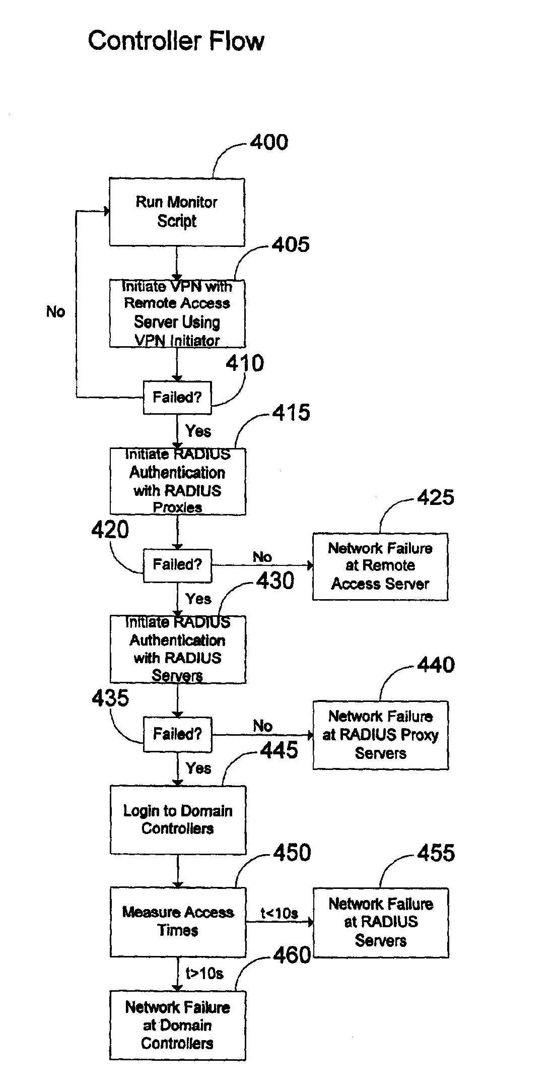
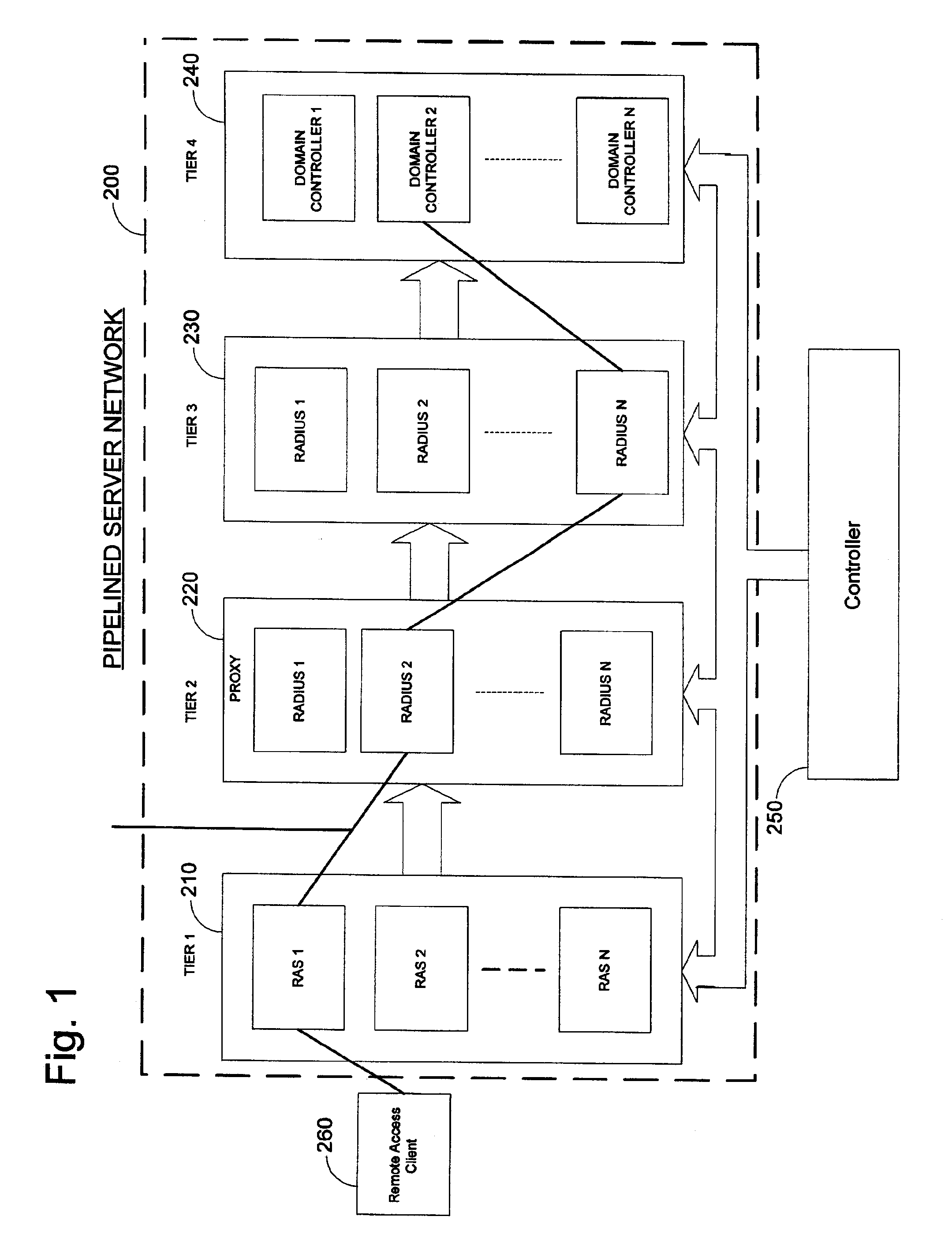
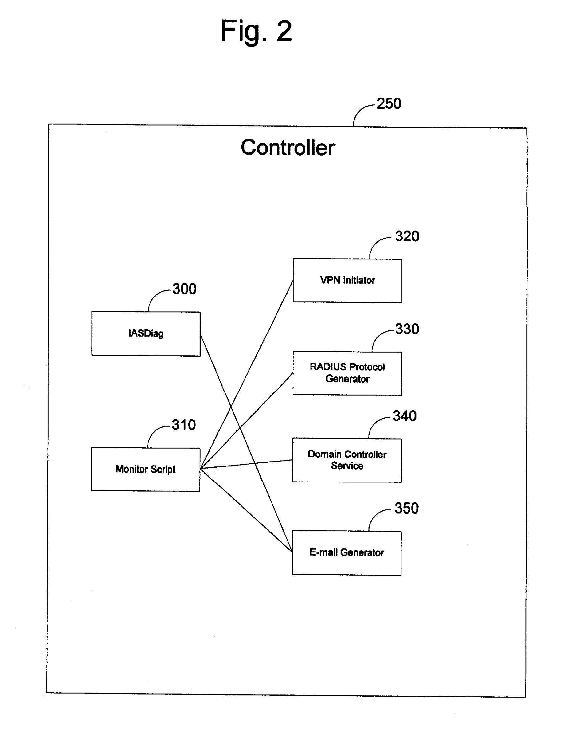
[0027]Turning to the drawings, wherein like reference numerals refer to like elements, the invention is described hereinafter in the context of a computing environment. Although it is not required for practicing the invention, the invention is described as it is implemented by computer-executable instructions, such as program modules, that are executed by a computer. Generally, program modules include routines, programs, scripts, objects, components, data structures and the like that perform particular tasks or implement particular abstract data types.

[0028]In the following description, the invention is described with reference to acts and symbolic representations of operations performed by one or more computers, unless indicated otherwise. Such acts and operations, which are at times referred to as being computer-executed, include the manipulation by the processing unit of the computer of electrical signals representing data in a structured form. This manipulation transforms the da...


PUM


Abstract

This invention relates to a diagnostic tool for networks that process messages in stages such as pipelined networks. In a pipelined network comprising tiers of servers, each tier of servers communicates only with adjacent tiers in a communications flow that processes messages in a sequence of tiers. The tool requires a controller located locally with respect to the pipelined network for generating messages to be processed by the pipelined network. Communication paths connect the controller to each tier of the pipelined network. A program executing at the controller detects a failure of the processing of the message by the pipelined network and receives diagnostic information from the tiers after the failure is detected. The diagnoses based on the retrieved information can proceed either manually or automatically, depending on how the information is collected. In order to automate the diagnosis, the program executing on the controller includes commands for sequentially analyzing each tier in the pipelined network in order to isolate the tier in which the failure occurred. For manual diagnosis, the program includes commands for simultaneously (or almost simultaneously) requesting information from each tier upon network failure. In the manual approach, distributed agents at all of the tiers gather information about the operating of the tier at the time of network failure.

Description

TECHNICAL FIELD[0001]This invention relates generally to error diagnosis in a network and, more particularly, relates to facilitating a sequential analysis of a pipelined network in response to network errors in order to isolate and troubleshoot the problem.BACKGROUND OF THE INVENTION[0002]As the Internet has grown from a few servers controlled by the government and a few educational institutions into a vast, heterogeneous network of servers and clients, the demands on servers and a corresponding interest in computer security have grown as well. As a result, servers have become more and more specialized, and networks have become more efficient, providing limited functionality to limited sets of users. In the interests of computer security, the sensitive information stored on servers has also been moved farther away from those users, and requests to access or manipulate that data must often pass through specialized tiers of servers before communicating with the machines actually carr...

Claims


Application Information

Patent Timeline
Patent Type & Authority Patents(United States)
IPC IPC(8): G06F11/00H04L1/22H04L12/24H04L12/26
CPCH04L1/22H04L43/0823H04L43/06H04L41/0659H04L41/046
Inventor BHAT, THIRUMYALESHWODRICH, MARKCACKA, EVAN C.
Owner MICROSOFT TECH LICENSING LLC
Why Eureka
Try Eureka