Technique for enabling traffic engineering on CE-CE paths across a provider network

a technology of provider network and traffic engineering, applied in the field of computer networks, can solve the problems of path computation at the head-end lsr, inability to distribute te information regarding pe-ce links across the provider network to other pes, and inability to communicate with one of the neighboring nodes

Active Publication Date: 2007-06-14
CISCO TECH INC
View PDF4 Cites 196 Cited by
  • Summary
  • Abstract
  • Description
  • Claims
  • Application Information

AI Technical Summary

Benefits of technology

[0025] The present invention is directed to a technique for enabling Traffic Engineering (TE) on paths between customer edge devices (CEs) across a provider network (“CE-CE paths”) in a computer network. According to the novel technique, TE is configured on a link from a sending provider edge device (PE) to a first CE (“PE-CE link”), e.g., a CE of one or more virtual private networks (VPNs). The sending PE conveys TE information of the PE-CE link to one or more receiving PEs in the provider network. Upon receiving the TE information, each receiving PE expands a TE database (TED) for information regarding the provider network (i.e., a “core TED”) to include TE-configured PE-CE links, e.g., by updating one or more corresponding VPN TEDs (VTEDs) for each VPN maintained by the receiving PE. Once the receiving PEs have the TE information for configured PE-CE links from the provider network, one or more TE techniques may be applied to paths from a second CE of the receiving PE to the first CE (a CE-CE path) to thereby facilitate, e.g., establishment of TE-LSPs along CE-CE paths.
[0030] Advantageously, the novel technique enables TE on CE-CE paths in a computer network. By conveying TE information for PE-CE links, the novel technique allows PEs of the provider network to expand their TE topologies to include the PE-CE links. Accordingly, by including TE information for PE-CE links, the novel technique allows for TE techniques to be applied to CE-CE paths. Particularly, MPLS TE-LSPs may be efficiently created along CE-CE paths. Also, the dynamic nature of the novel technique alleviates the need for cumbersome manual configuration.

Problems solved by technology

For example, the node may become unable to communicate with one of its neighboring nodes, e.g., due to a link failure between the nodes or the neighboring node failing, such as going “off line,” etc.
One difficulty that arises in crossing domain boundaries is that path computation at the head-end LSR requires knowledge of network topology and resources across the entire network between the head-end and the tail-end LSRs.
Yet service providers typically do not share this information with each other across domain borders.
One problem associated with MPLS / VPN networks is their current inability to distribute TE information regarding PE-CE links across the provider network to other PEs.
However, this solution does not provide TE information of the PE-CE links, such as, e.g., the dynamically measured IP bandwidth, reserved MPLS bandwidth, color, etc. of the PE-CE links.
This solution suffers numerous problems, however, such as VPN private addressing constraints, i.e., where CEs of different VPNs may share the same address, which may cause route confusion at receiving devices.
Also, a lack of scalability may exist considering the possible number of PE-CE links (e.g., hundreds of thousands), which may surpass the limitations of internal route leaking (e.g., of IGP messages), thus possibly causing fragmented messages, error messages, etc., as will be understood by those skilled in the art.
This lack of scalability may also apply to attempts to manually configure TE information, which would be overly cumbersome given the dynamic nature of TE information.
As a result of the inability to efficiently distribute dynamic TE information, various TE techniques may not be applied to the PE-CE links from other PEs not attached to the PE-CE links.
For example, current MPLS / VPN networks do not have the ability to efficiently create TE tunnels (e.g., MPLS TE-LSPs) along CE-CE paths, such as for reserved bandwidth, fast convergence, fast re-route (FRR), diverse paths, etc.

Method used


Image

  • Technique for enabling traffic engineering on CE-CE paths across a provider network
  • Technique for enabling traffic engineering on CE-CE paths across a provider network
  • Technique for enabling traffic engineering on CE-CE paths across a provider network

Examples


Embodiment Construction

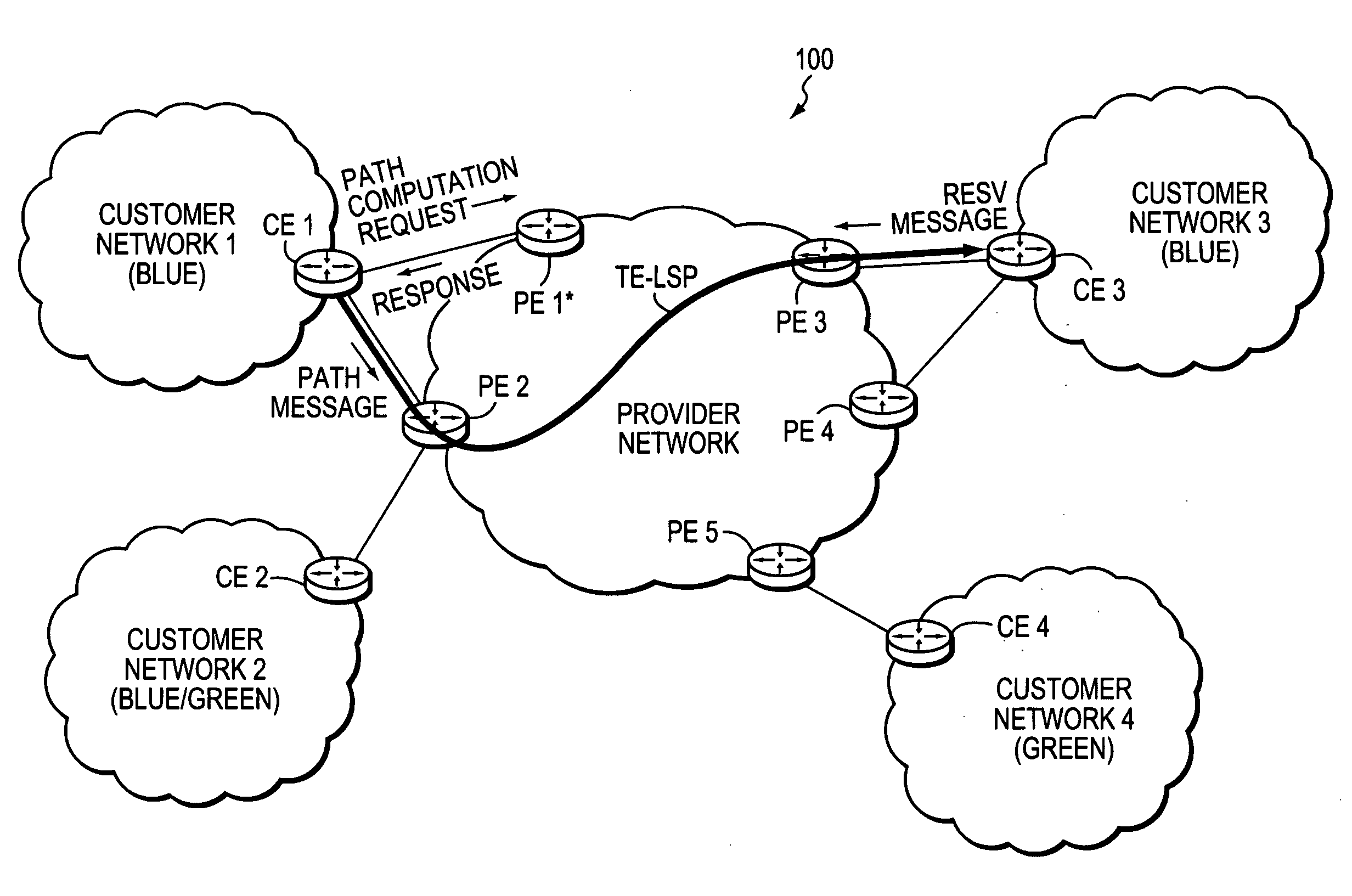
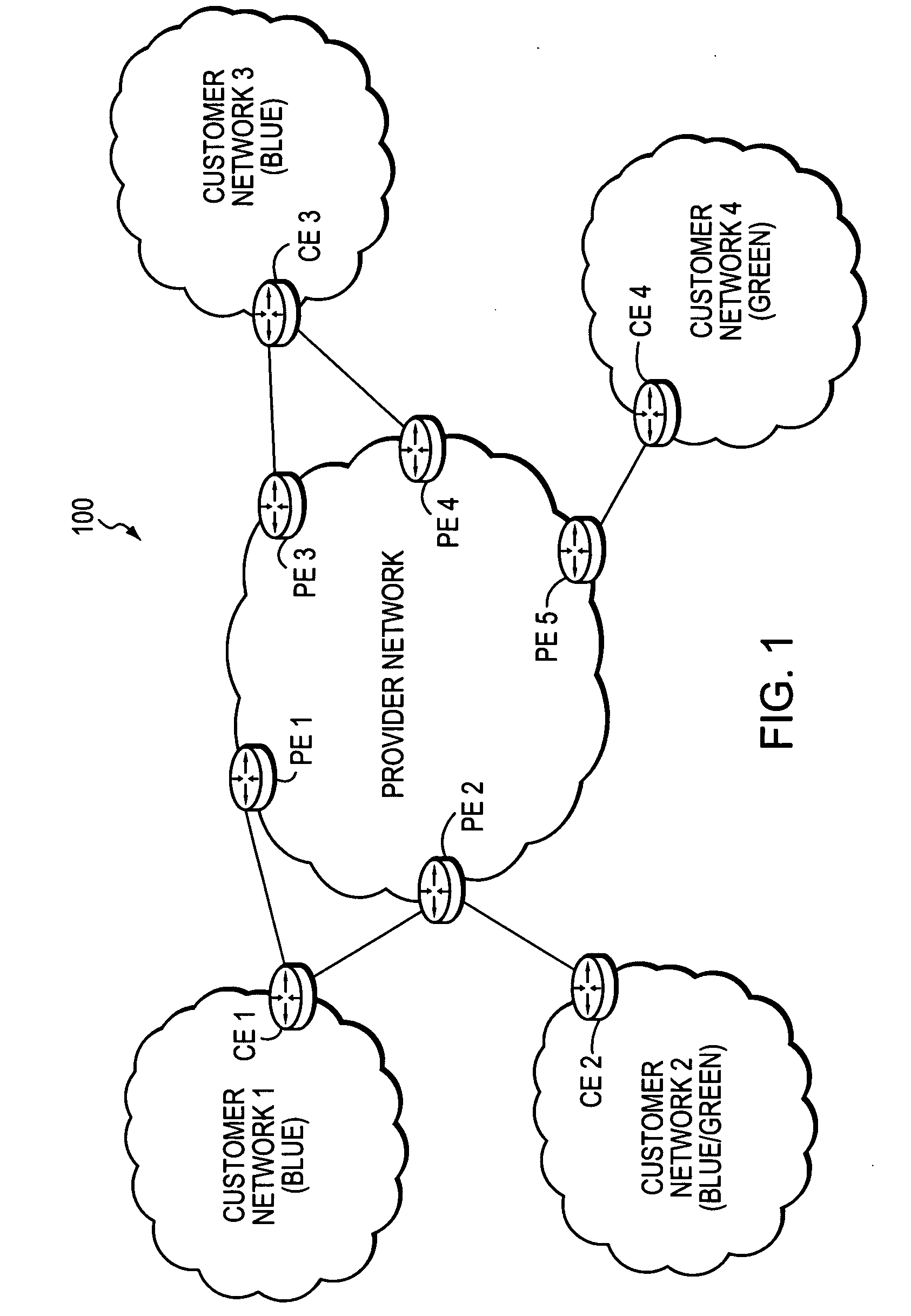
[0044]FIG. 1 is a schematic block diagram of an exemplary computer network 100 comprising a provider network, (e.g., a service provider network) interconnected to one or more customer networks (customer networks 1-4). Although the provider and customer networks are described illustratively herein as autonomous systems, those skilled in the art will appreciate that they may be configured as one or more routing domains or other networks or subnetworks. The provider network comprises one or more network nodes, including a set of communicating border nodes or routers (illustratively, provider edge devices, or “PEs”) PE1-PE5, through which client communications, such as data packet traffic, can pass into and out of the provider network. The network comprises provider devices (Ps) (not shown) configured to communicate traffic and information internally within the provider network.

[0045] The customer networks 1-4 also comprise one or more network nodes, including a set of communicating bo...


PUM


Abstract

A technique enables Traffic Engineering (TE) on paths between customer edge devices (CEs) across a provider network (“CE-CE paths”) in a computer network. According to the novel technique, TE is configured on a link from a sending provider edge device (PE) to a first CE (“PE-CE link”), e.g., a CE of one or more virtual private networks (VPNs). The sending PE conveys TE information of the PE-CE link to one or more receiving PEs in the provider network. Upon receiving the TE information, each receiving PE expands a TE database (TED) for information regarding the provider network (i.e., a “core TED”) to include TE-configured PE-CE links, e.g., by updating one or more corresponding VPN TEDs (VTEDs) for each VPN maintained by the receiving PE. Once the receiving PEs have the TE information for configured PE-CE links from the provider network, one or more TE techniques may be applied to paths from a second CE of the receiving PE to the first CE (a CE-CE path) to thereby facilitate, e.g., establishment of TE-LSPs along CE-CE paths.

Description

BACKGROUND OF THE INVENTION [0001] 1. Field of the Invention [0002] The present invention relates to computer networks and more particularly to traffic engineering (TE) between customer edge devices (CEs) across a provider network in a computer network. [0003] 2. Background Information [0004] A computer network is a geographically distributed collection of interconnected subnetworks, such as local area networks (LAN) that transport data between network nodes. As used herein, a network node is any device adapted to send and / or receive data in the computer network. Thus, in this context, “node” and “device” may be used interchangeably. The network topology is defined by an arrangement of network nodes that communicate with one another, typically through one or more intermediate nodes, such is as routers and switches. In addition to intra-network communications, data also may be exchanged between neighboring (i.e., adjacent) networks. To that end, “edge devices” located at the logical ...

Claims


Application Information

Patent Timeline
Patent Type & Authority Applications(United States)
IPC IPC(8): H04L12/26
CPCH04L45/02H04L45/50
Inventor VASSEUR, JEAN-PHILIPPE
Owner CISCO TECH INC
Why Eureka
Try Eureka