Switch failover control in a multiprocessor computer system

a multi-processor computer system and failover control technology, applied in the field of processing, can solve problems such as switches

Inactive Publication Date: 2011-12-29
IBM CORP
View PDF11 Cites 178 Cited by
  • Summary
  • Abstract
  • Description
  • Claims
  • Application Information

AI Technical Summary

Benefits of technology

[0004]An exemplary embodiment is a computer implemented method for failover control within a computer system. The method includes maintaining a primary device table entry (DTE) in a first device table activated for a first adapter in communication with a first host processor node having a first root complex via a first switch assembly and maintaining a secondary DTE in standby for a second adapter in communication with a second host processor node having a second root complex via a second switch assembly; maintaining a primary DTE in a second device table activated for the second adapter and maintaining a secondary DTE in standby for the first adapter; and upon a failover condition, updating the secondary DTE in the first device table as an active entry for the second adapter and forming a failover path to enable traffic to route from the second adapter through the second switch assembly over to the first switch assembly and up to the first root complex of the first host processor node.
[0005]Another exemplary embodiment is a computing system for failover control. The system includes a first host processor node with a first root complex in communication with a first adapter via a first switch assembly; a second host processor node with a second root complex in communication with a second adapter via a second switch assembly; a first device table in the first host processor node, the first device table includes a primary device table entry (DTE) activated for the first adapter and a secondary DTE in standby for the second adapter; and a second device table in the second host processor node, the second device table includes a pr...

Problems solved by technology

I/O adapters or peripheral devices are connected to a primary processor node and to a secondary failover processor node through i...

Method used


Image

  • Switch failover control in a multiprocessor computer system
  • Switch failover control in a multiprocessor computer system
  • Switch failover control in a multiprocessor computer system

Examples


Embodiment Construction

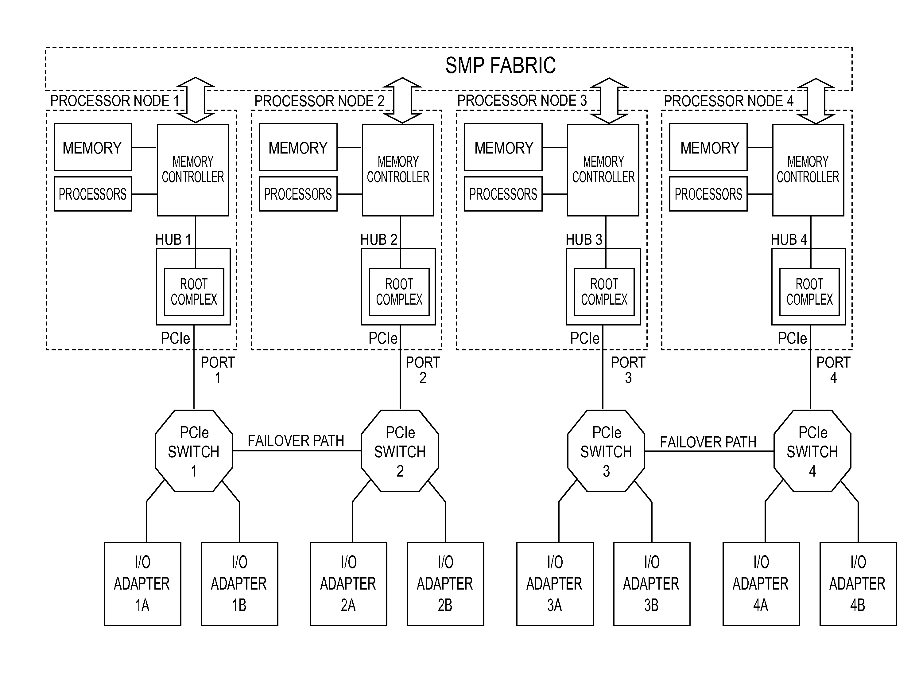
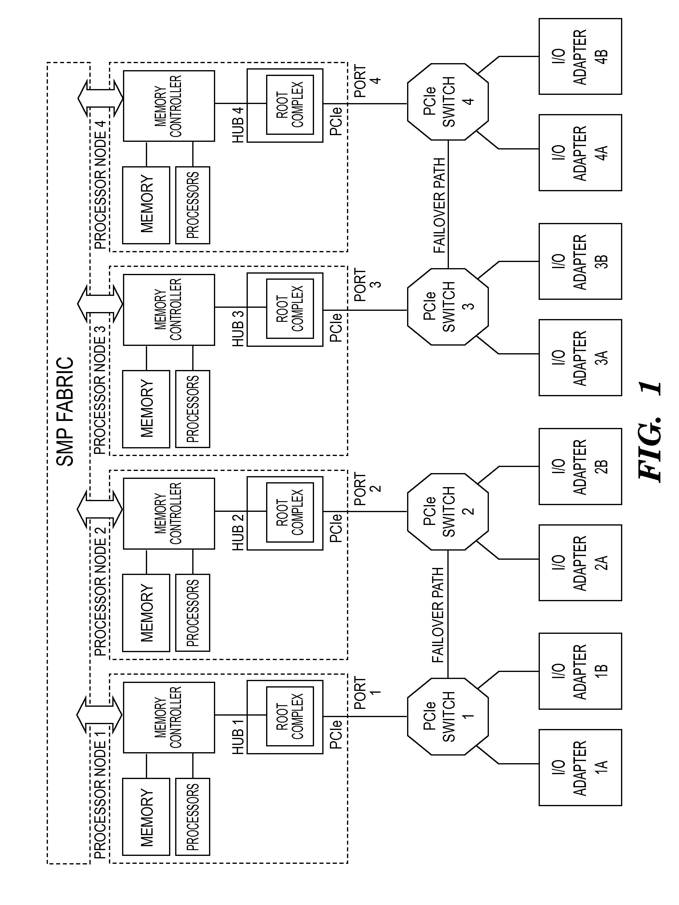
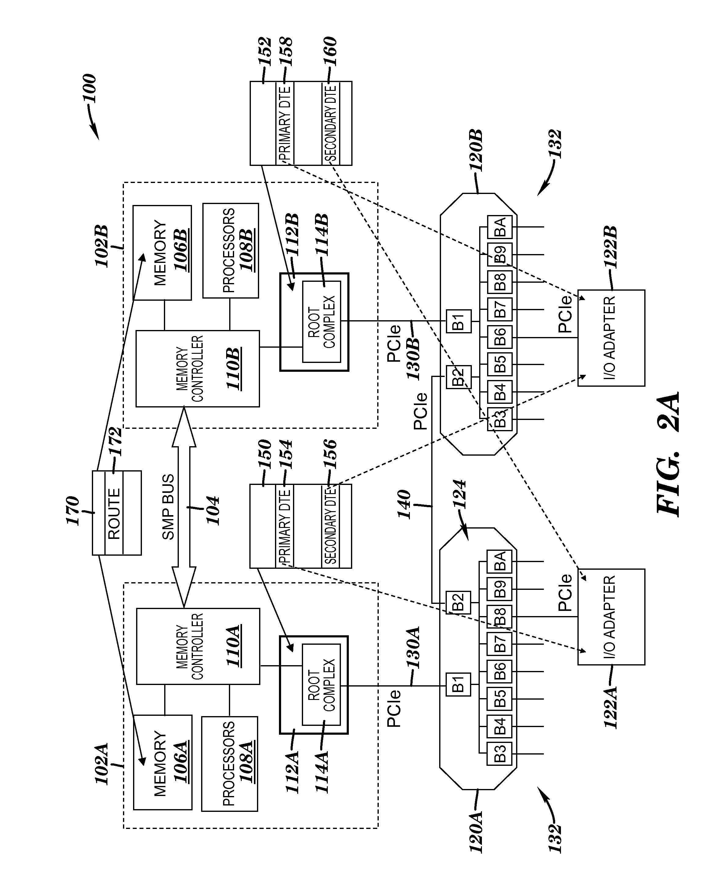
[0016]Exemplary embodiments of the present invention provide systems and methods for failover control in a multi-processor computing system. In an exemplary embodiment, the computing system supports controlled and surprise failover conditions as well as control failback conditions by enabling traffic from a failed processor node to flow over an operational or surviving processor node. One way of establishing if an adapter is operational is described in commonly assigned U.S. patent application Attorney Docket No. POU920100018US1, entitled “CONTROLLING THE SELECTIVELY SETTING OF OPERATIONAL PARAMETERS FOR AN ADAPTER” Jun. 23, 2010, which is incorporated by reference herein in its entirety. This can be accomplished using off-the-shelf Peripheral Component Interconnect express (PCIe) fan-out chips (i.e., switches) according to an exemplary embodiment. In accordance with one exemplary embodiment, the computing system has device table entries for each peripheral device at each processor ...


PUM


Abstract

A system and a method for failover control comprising: maintaining a primary device table entry (DTE) in a first table activated for a first adapter in communication with a first processor node having a first root complex via a first switch assembly and maintaining a secondary DTE in standby for a second adapter in communication with a second processor node having a second root complex via a second switch assembly; maintaining a primary DTE in a second table activated for the second adapter and maintaining a secondary DTE in standby for the first adapter; and upon a failover, updating the secondary DTE in the first table as an active entry for the second adapter and forming a path to enable traffic to route from the second adapter through the second switch assembly over to the first switch assembly and up to the first root complex of the first processor node.

Description

BACKGROUND[0001]This invention relates generally to processing within a computing environment, and more particularly to switch failover control in a multi-processor computer system.[0002]Today's computing platforms and processing system are moving toward an I / O interconnect topology that provides a single communication path between each peripheral device and the host. These computing platforms and processing systems may use packetized communications within the tree structure. Examples of such computing platforms and processing systems include what is referred to as, for example, peripheral component interconnect (PCI) systems and PCI Express (PCIe) systems. Peripheral devices are discovered by such platforms and systems through an enumeration process performed by a host system element.[0003]I / O adapters or peripheral devices are connected to a primary processor node and to a secondary failover processor node through its I / O expansion network consisting of pairs of interconnected pro...

Claims


Application Information

Patent Timeline
IPC IPC(8): G06F11/16G06F13/00G06F11/00
CPCG06F11/2033G06F11/2043G06F11/2038
Inventor BAYER, GERD K.CRADDOCK, DAVID F.GREGG, THOMAS A.JUNG, MICHAELKOHLER, ANDREASNASS, ELKE G.SCHLAG, OLIVER G.SZWED, PETER K.
Owner IBM CORP
Why Eureka
Try Eureka