Multiple tool attachment system

a multi-tool, attachment system technology, applied in the direction of portable power-driven tools, manufacturing tools, building repairs, etc., can solve the problems of independent cylinders, patents that do not optimize the jaw structure for cutting, and distinct tools of equipment, so as to achieve convenient conversion, optimize the ratio between the jaw and the power structure of the jaw, and optimize the effect of the jaw structur

Inactive Publication Date: 2006-02-07
RAMUN JOHN R
View PDF18 Cites 44 Cited by
  • Summary
  • Abstract
  • Description
  • Claims
  • Application Information

AI Technical Summary

Benefits of technology

[0011]The object of the present invention is to overcome the aforementioned drawbacks of the prior art. It is a further object of the present invention to provide a multiple tool attachment system which is easily converted between a plurality of distinct tools. A further object of the present invention is to provide a demolition tool having a plurality of movable jaws which optimizes the jaw structure. A further object of the present invention is provide a demolition tool which optimizes the ratio between the jaw and the jaw power structure to provide optimum power performance throughout the blade movement cycle. A further object of the present invention is to provide a demolition tool system that simplifies the construction of the tool system, including rotating tools. A further object of the present invention is to provide a method for designing a demolition tool and tool system.
[0014]In one embodiment of the invention, the universal body includes a guide slot extending longitudinally along the body. A slide member is received within the guide slot, with each linkage attached to the slide member and the piston cylinder arrangement attached to the body and coupled to the slide member for moving the slide member and the blades. The linkages may be attached to the slide member at a common point. Additionally, the linkages may have a common sleeve adapted to hold the linkages together when decoupled from the slide member. The universal body may be provided with pivotable sides and / or with side access panels to assist in repair, maintenance and tool changing.

Problems solved by technology

Historically, all of these pieces of equipment represent distinct tools having significant independent capital cost.
However, these patents do not optimize the jaw structure for the purpose of cutting.
Additionally, the independent cylinders increase the cost and prevent a compact shear design.
The prior art does not provide a system for easily changing tools or a system which allows complete separate tools to efficiently share a common structure.
Further, the prior art fails to optimize the jaw structure utilized in the individual tools, such as metal cutting shears, to maximize power and efficiency.
Additionally, the prior art provides a complex arrangement for rotations of the tool and jaws without sufficient protection for any hydraulic cylinder is powering the working jaws.

Method used


Image

  • Multiple tool attachment system
  • Multiple tool attachment system
  • Multiple tool attachment system

Examples


Embodiment Construction

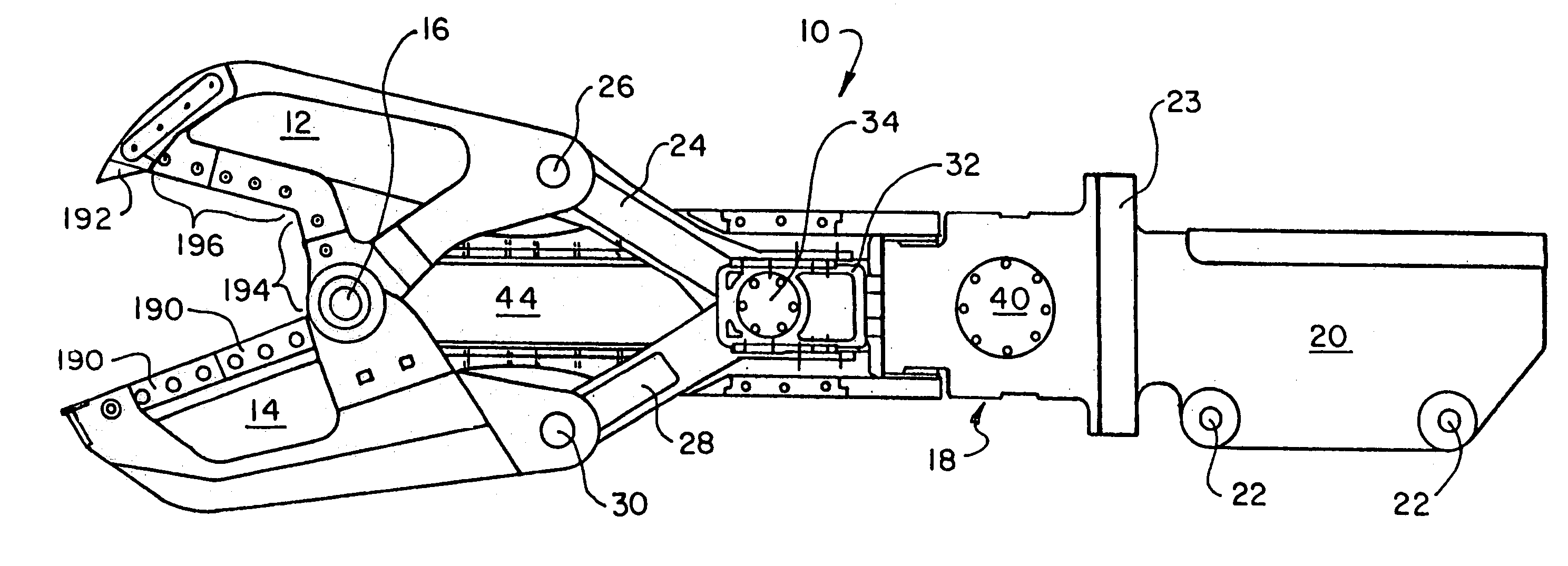
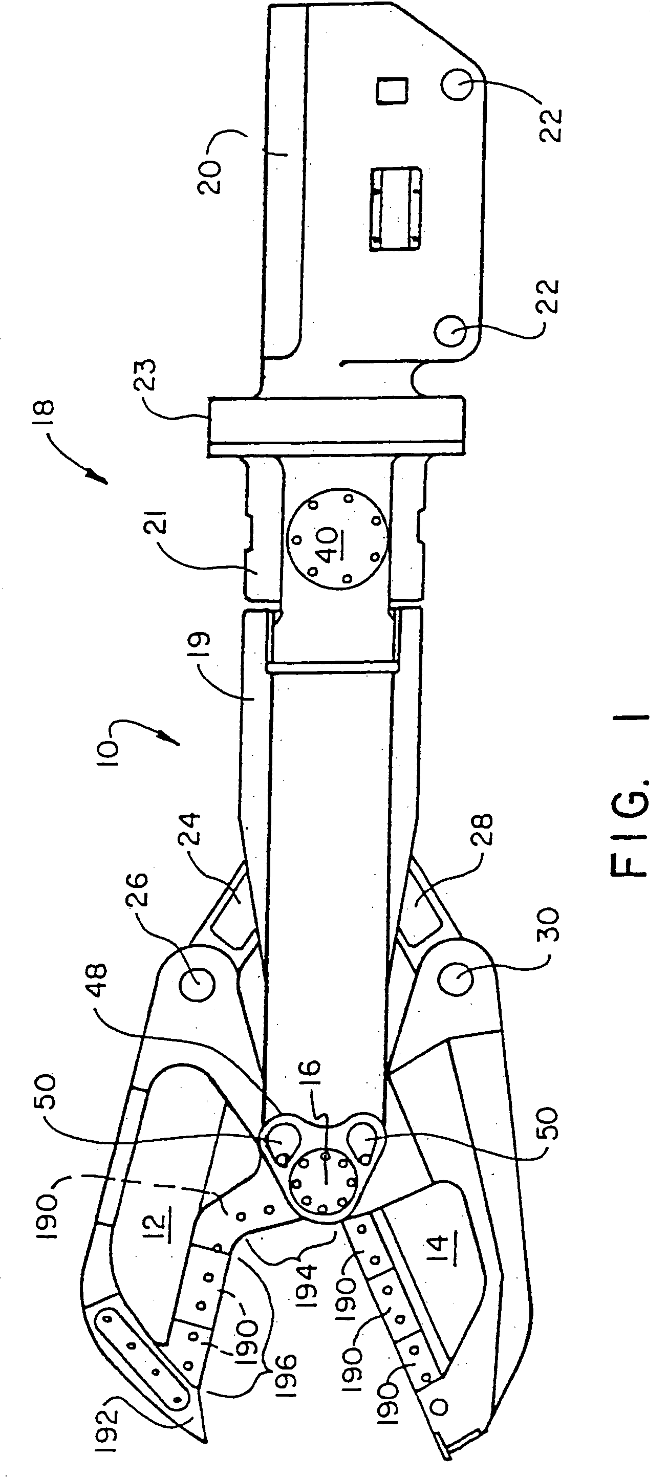
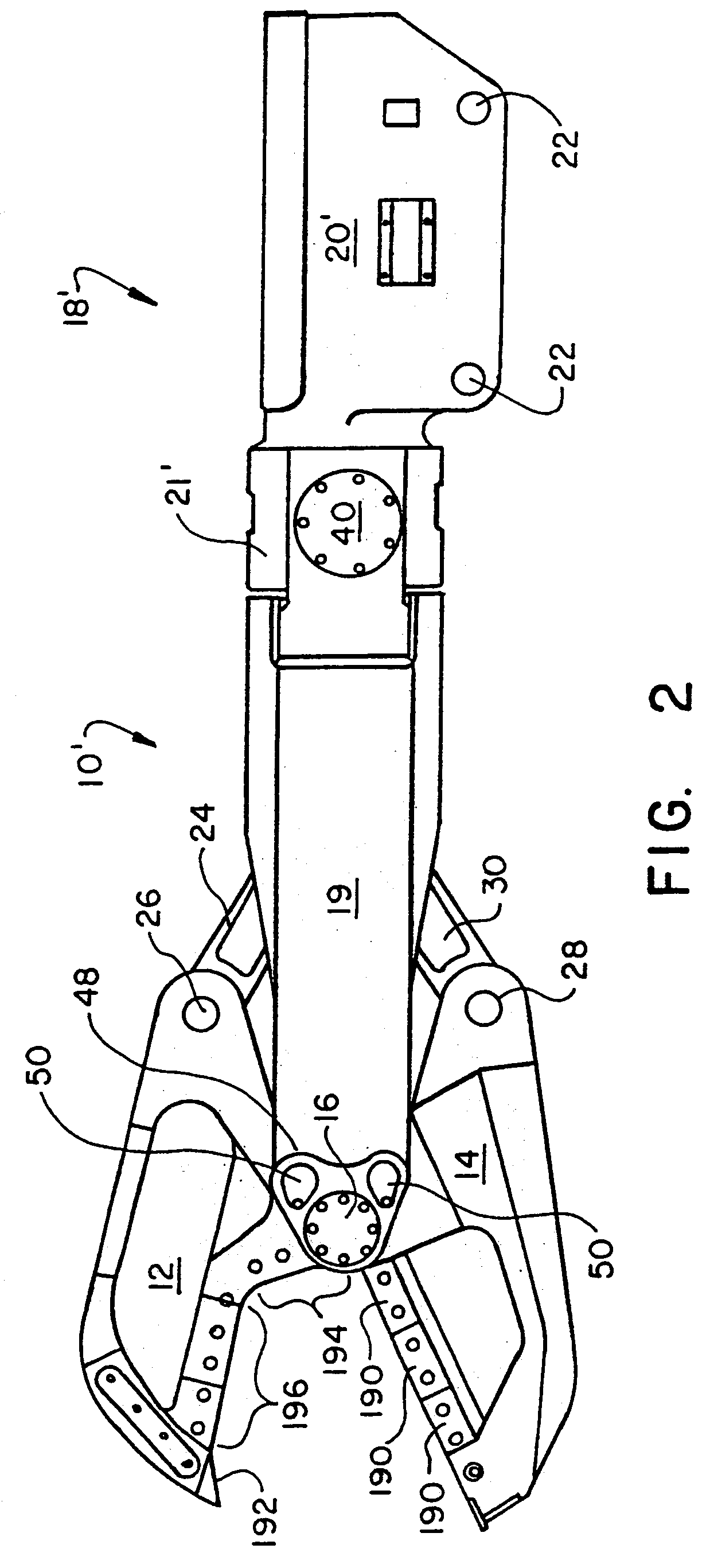
[0071]FIG. 1 illustrates a multiple tool attachment according to the present invention adapted to be attached to demolition equipment, such as a backhoe (not shown). The multiple tool attachment is adapted to connect one of a series of tools or tool units to the demolition equipment.

[0072]FIG. 1 illustrates a shear 10 coupled to the multiple tool attachment. The shear 10 includes a first blade 12 and second blade 14 pivotally connected at a hub or main pin 16 to a universal body 18. The universal body 18 is referred to as the universal body 18 because it remains common to a series of tools or tool units in the attachment system according to the present invention. The universal body 18 is comprised of sides 19, bearing housing 20 and yoke 21. The main pin 16 provides a common pivot for both the first blade 12 and second blade 14.

[0073]The bearing housing 20 includes spaced mounting apertures 22 for attaching the universal body 18 to the demolition equipment in a conventional fashion ...


PUM

PropertyMeasurementUnit
anglesaaaaaaaaaa
anglesaaaaaaaaaa
lengthaaaaaaaaaa

Abstract

A multiple attachment system is adapted to be attached to demolition equipment. The system includes a universal body attached to the demolition equipment. A series of tools is independently attached to the universal body. The universal body includes a guide slot extending longitudinally along the universal body. Each tool includes a pair of pivotable jaws adapted to pivotably attach to the universal body with at least one linkage extending from the universal body and attachable to each jaw of the tool. A slide member is received within the guide slot, with each linkage attached to the slide member, and a piston cylinder arrangement is attached to the universal body and coupled to the slide member for moving the slide member and the jaws. The multiple tool attachment system is provided with quick change features and is designed to optimize the cutting characteristics throughout the movement cycle.

Description

CROSS RELATED APPLICATIONS[0001]This application claims the benefit of U.S. Provisional Application Ser. No. 60 / 195,797, filed Apr. 10, 2000 which claims the benefit of U.S. Provisional Application Serial No. 60 / 159,869 filed Oct. 15, 1999BACKGROUND OF THE INVENTION[0002]1. Field of the Invention[0003]The present invention relates to a tool attachment system for construction or demolition equipment which is adapted to be attached to a backhoe for attaching multiple tools, such as a heavy-duty metal cutting shear, a plate shear, a concrete crusher, a grapple or the like. More particularly, the present invention relates to a multiple tool attachment system for attaching tools having plural movable jaws.[0004]2. Background Information[0005]The present application refers to demolition equipment, however, the equipment is also referred to as construction equipment, scrap handling equipment and the like. The description of demolition equipment or construction equipment is not intended to ...

Claims


Application Information

Patent Timeline
Patent Type & Authority Patents(United States)
IPC IPC(8): B02C1/04A62B3/00B23D17/00B23D31/00E02F3/96
CPCA62B3/005B23D17/00B23D31/008E02F3/3636E02F3/965E02F9/006B23D17/06E02F3/3677Y10T29/49766Y10T29/49764E04G23/082
Inventor RAMUN, JOHN R.
Owner RAMUN JOHN R
Why Eureka
Try Eureka