
Grease replenishing device

a replenishing device and grease technology, applied in mechanical devices, lubricant transfer, manufacturing tools, etc., can solve the problems of little or no mechanism for controlling the amount of grease to be supplied into high rotary speed rolling bearings, rapid heat generation, etc., and achieve the effect of prolonging the life of them

Inactive Publication Date: 2006-02-07
NSK LTD
View PDF27 Cites 19 Cited by
  • Summary
  • Abstract
  • Description
  • Claims
  • Application Information

AI Technical Summary

Benefits of technology

The present invention provides a grease replenishing device for replenishing a grease-lubricated rolling device with a grease. The device includes a storage chamber for storing a grease and a pressing member for pushing the grease out of the chamber into the interior of the rolling bearing. This device can timely and accurately replenish the grease in the rolling bearing, keeping it lubricated over an extended period of time and preventing rapid heat generation and improper lubrication resulting in seizing of the bearing. The pressing member may be a piston or a screw, and the device may also include a feed passage for allowing the grease to flow into the rolling bearing. The technical effect of this invention is to prolong the lifetime of the bearing and improve its performance.

Problems solved by technology

However, little or no mechanisms for controlling the amount of grease to be supplied into a high rotary speed rolling bearing have been put to practical use.
When a rolling bearing operates at a high rotary speed while being replenished with a grease without sufficient control, possible excessive rise of the amount of grease causes rapid heat generation or possible excessive reduction of the amount of grease causes improper lubrication of the bearing leading to seizing.

Method used


Image

  • Grease replenishing device
  • Grease replenishing device
  • Grease replenishing device

Examples


first embodiment

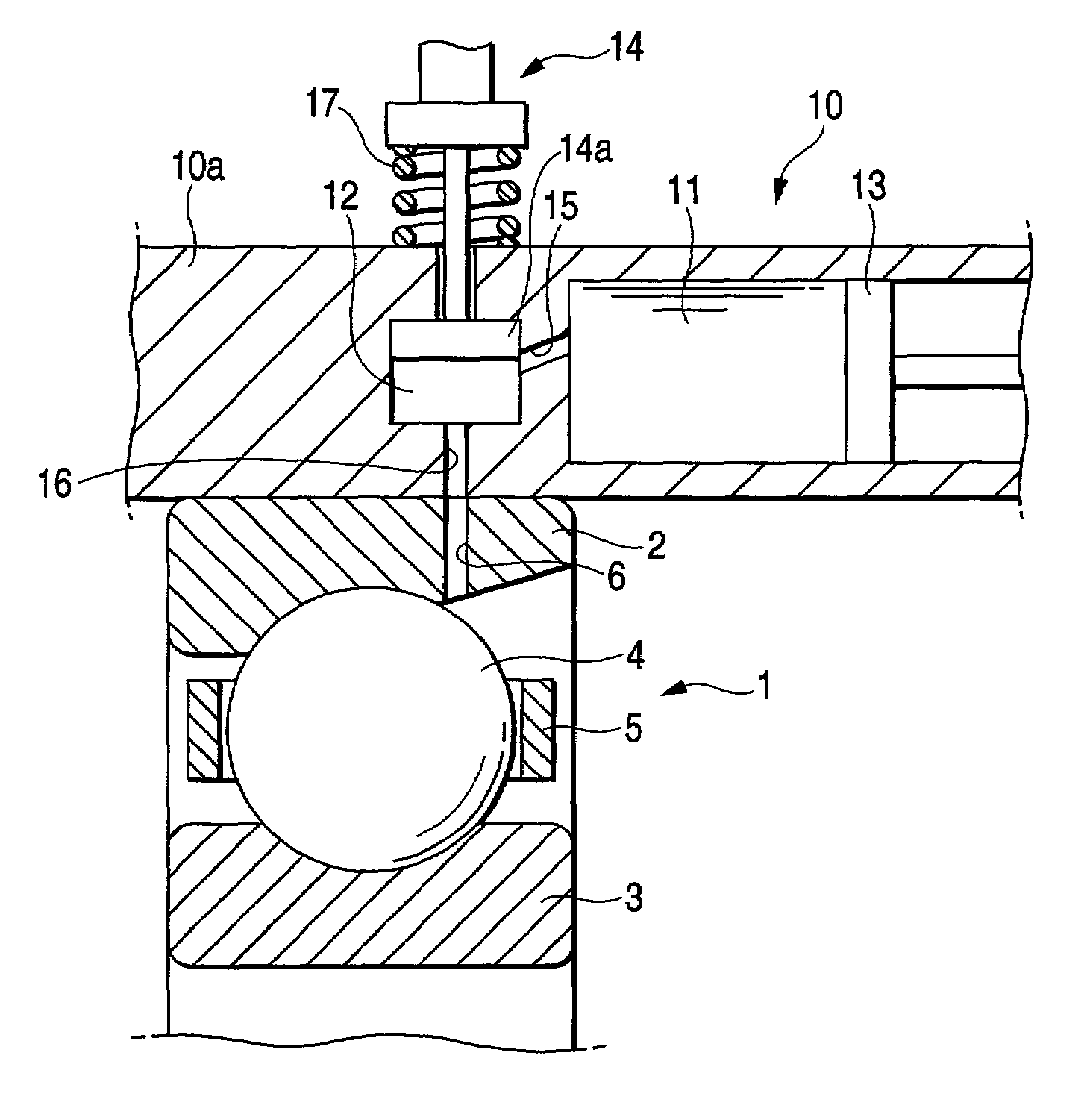
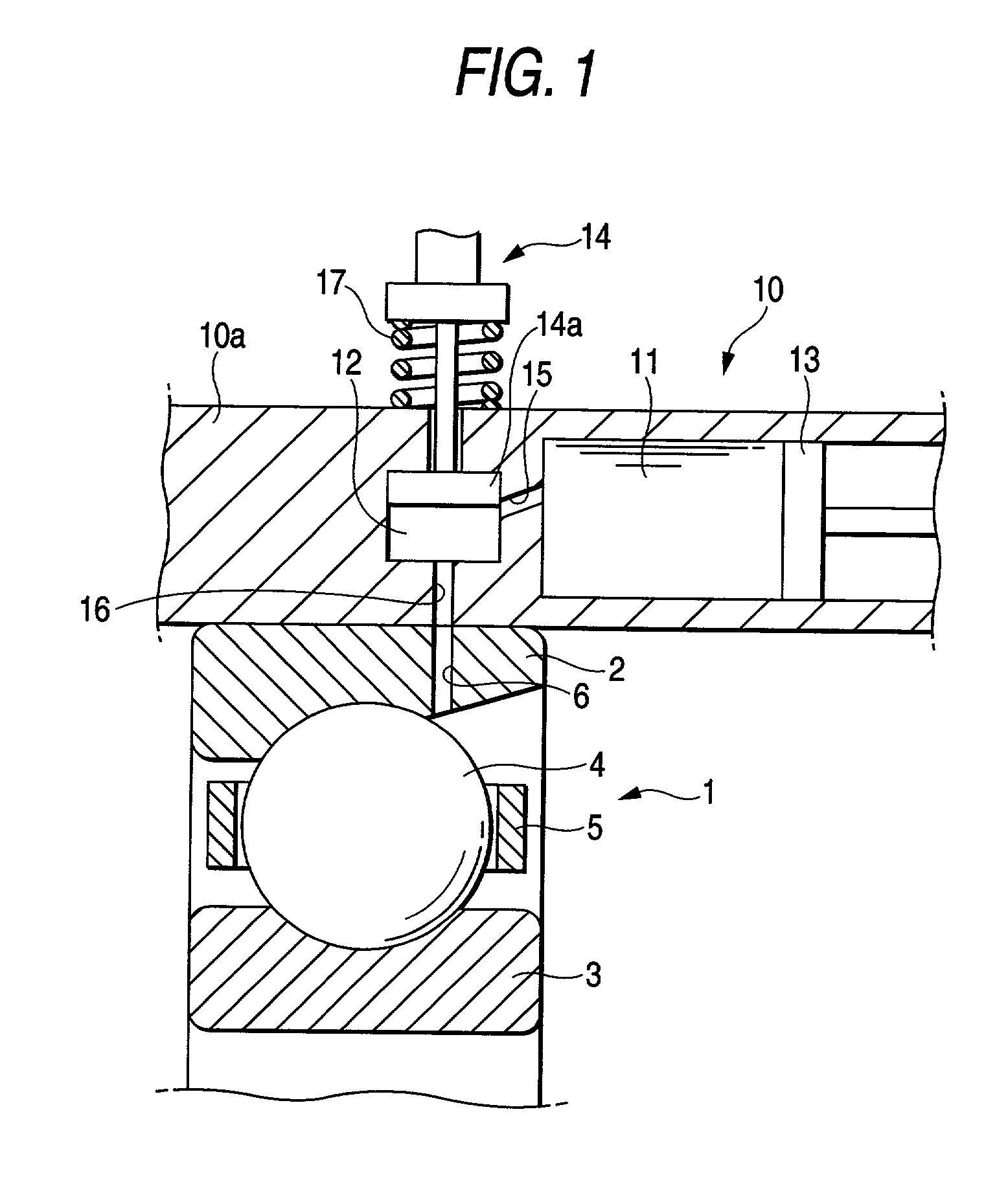
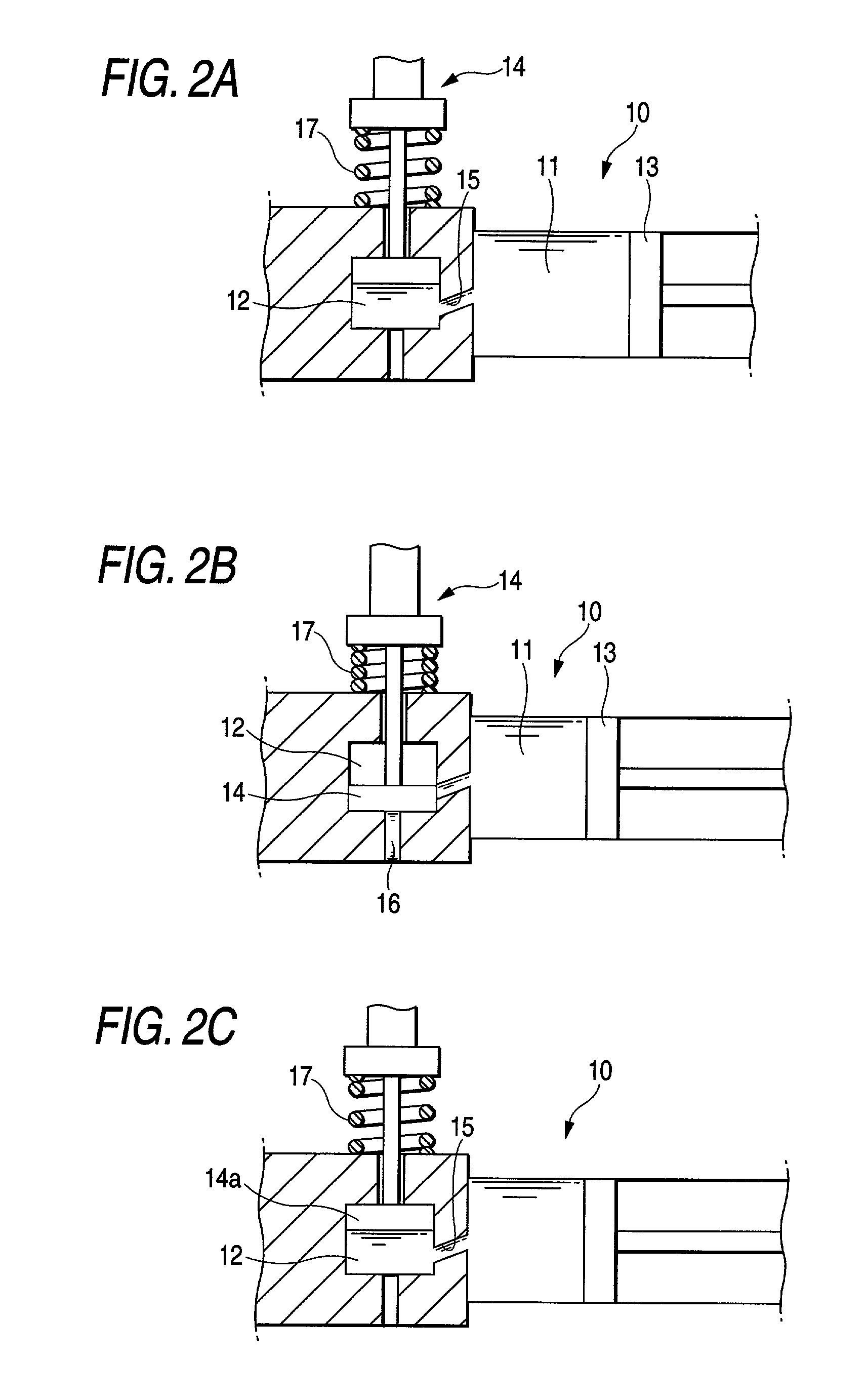
[0026]FIG. 1 is a sectional view illustrating the grease replenishing device of the invention. A rolling bearing (ball bearing) 1 to be replenished with a grease generally comprises an outer ring 2, an inner ring 3, rolling elements (balls) 4 rotatably interposed between the outer ring 2 and the inner ring 3, and a retainer 5 for rollably retaining the rolling elements at regular intervals along the periphery of the rolling bearing.

[0027]The rolling bearing 1 is arranged such that the outer surface of the outer ring 2 is fitted on the inner surface of a housing 10a. In the outer ring 2 is formed a grease supply hole 6 which communicates to the interior of the rolling bearing 1 and opens at the inner surface of the outer ring so that the grease supplied from a grease replenishing device 10 can flow into the interior of the rolling bearing.

[0028]The grease replenishing device 10 comprises a first storage chamber 11 for previously storing a grease and a second storage chamber 12 for re...

second embodiment

[0042]the grease replenishing device of the invention will be described in connection with FIG. 3.

[0043]The rolling bearing 1 is arranged such that the outer surface of the outer ring 2 is fitted onto the inner surface of the housing 20a. The outer ring 2 has a grease supply hole 6 formed therein for supplying the grease from the grease replenishing device 20 thereinto as in the first embodiment.

[0044]The grease replenishing device 20 according to the present embodiment comprises a storage chamber 21 for previously storing the grease, a pressing member 24 for intermittently pushing a part of the grease stored in the storage chamber 21 out of the storage chamber 21 to supply a predetermined amount of the grease into the interior of the rolling bearing 1, and a feed passage 26 communicating between the storage chamber 21 and the rolling bearing 1 to supply the grease into the rolling bearing 1. The storage chamber 21, the pressing member 24 and the feed passage 26 are provided in a ho...


PUM


Abstract

A grease replenishing device replenishes a grease-lubricated rolling bearing with a grease. The grease replenishing device has a storage chamber portion and a pressing member. The storage chamber portion stores the grease. The pressing member pushes the grease out of the storage chamber into an interior of the rolling bearing.

Description

BACKGROUND OF THE INVENTION[0001]The present invention relates to a grease replenishing device for replenishing a grease-lubricated rolling device with a grease which bears a spindle that operates at a high rotary speed, etc.[0002]There are many mechanisms for replenishing a low rotary speed rolling bearing with a grease to prolong the lifetime thereof. However, little or no mechanisms for controlling the amount of grease to be supplied into a high rotary speed rolling bearing have been put to practical use.[0003]When a rolling bearing operates at a high rotary speed while being replenished with a grease without sufficient control, possible excessive rise of the amount of grease causes rapid heat generation or possible excessive reduction of the amount of grease causes improper lubrication of the bearing leading to seizing.SUMMARY OF THE INVENTION[0004]The invention has been worked out under these circumstances. It is an object of the present invention to provide a grease replenishi...

Claims


Application Information

Patent Timeline
Patent Type & Authority Patents(United States)
IPC IPC(8): F16C33/66F16N27/00B23Q11/12F16C33/58F16N11/08F16N11/10F16N37/00
CPCF16N37/003F16C33/6622F16C19/163F16C33/6607
Inventor NISHIBATA, SHINJIMORITA, YASUSHITAKANO, SUSUMU
Owner NSK LTD
Learn More