Electrical wiring system

a wiring system and electrical circuit technology, applied in the direction of couplings/cases, coupling device connections, tumbler/rocker switch details, etc., can solve the problems of labor-intensive, time-consuming, and expensive installation process of electrical circuits in buildings and/or other structures, and achieve cost-effectiveness, efficient system, and simplified installation process

Inactive Publication Date: 2006-02-07
PASS SEYMOUR
View PDF19 Cites 50 Cited by
  • Summary
  • Abstract
  • Description
  • Claims
  • Application Information

AI Technical Summary

Benefits of technology

[0007]The present invention addresses the problems described above. The present invention is directed to an electrical wiring system that simplifies the installation process. Further, the present invention provides an efficient system and method for terminating electrical devices. The system and method is cost-effective because it eliminates many of the labor intensive practices that are currently in use.

Problems solved by technology

Installing electrical circuits in buildings and / or other structures is typically labor intensive, time-consuming, and a process that requires electricians of various skill levels.
As a result the installation process is expensive.
This part of the installation process is the most costly and time consuming.

Method used


Image

  • Electrical wiring system
  • Electrical wiring system
  • Electrical wiring system

Examples


first embodiment

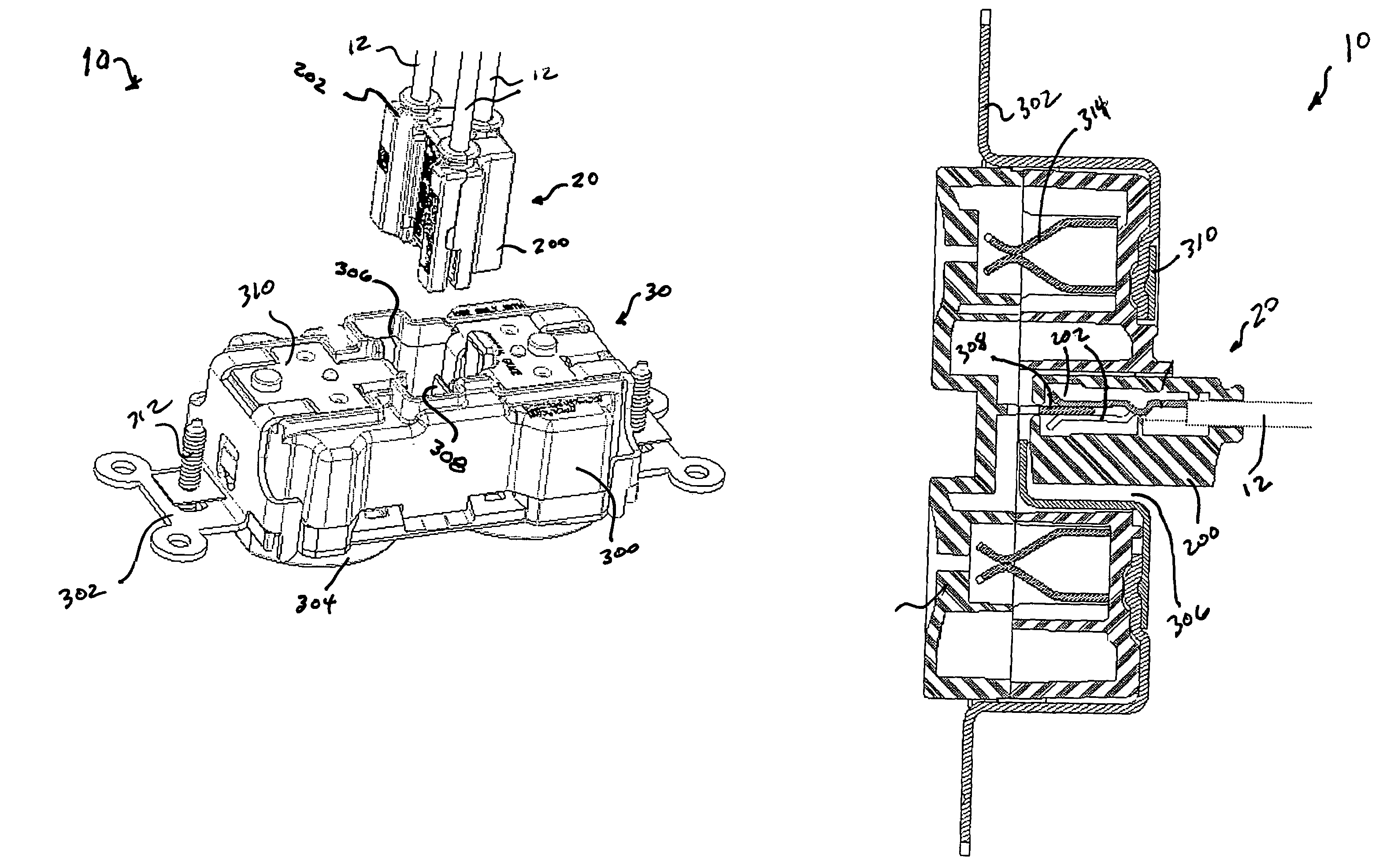
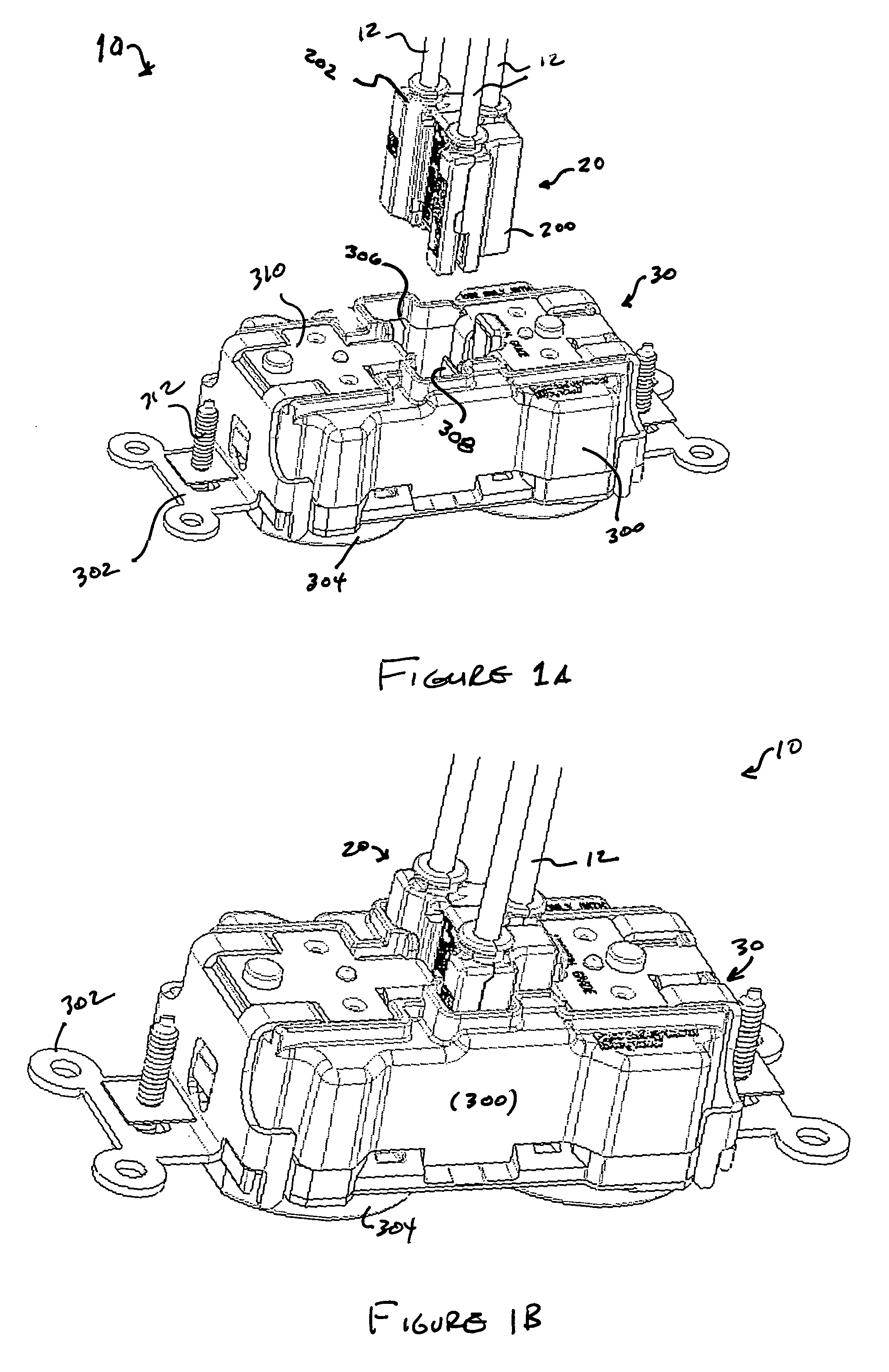
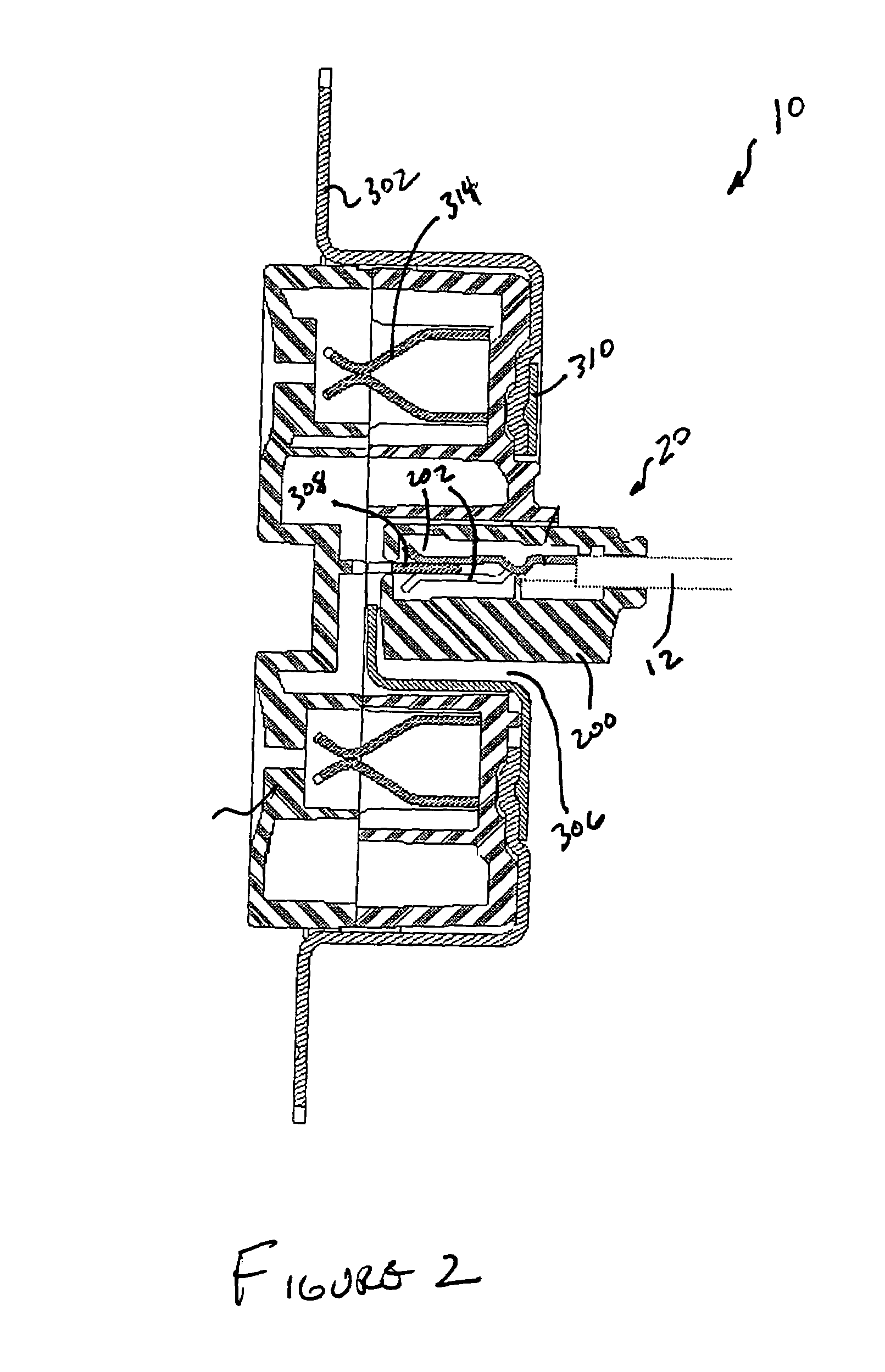
[0038]As embodied herein and depicted in FIG. 7, perspective view of plug connector 20 in accordance with the present invention is disclosed. Plug connector 20 includes upper housing 200 and lower housing 210. Upper housing 200 is snapped onto lower housing 210 to thereby enclose and terminate wires 12 in plug connector 20. Upper housing 200 includes latch mechanism 204. When plug connector 20 is inserted into receptacle 306, latch mechanism 204 prevents plug 20 from being pulled out of receptacle 306. Latch mechanism 204 is configured to meet Underwriter's Laboratory (UL) standards for a locking connector. In this case, UL requires that a static pull test of 201b be applied to the connector for one minute. During the test, plug connector 20 may not separate from receptacle 30.

[0039]During operation, latch mechanism 204 flexes upon insertion of plug connector 20. The flexure latch mechanism 204 relaxes to a non-flexed position upon successful locking of plug connector 20 to receptac...

second embodiment

[0041]As embodied herein and depicted in FIG. 9, a perspective view of the plug connector 40 is accordance with the present invention is disclosed. Plug connector includes upper housing 400 which is mated to lower housing 410. In this embodiment, the female contacts are replaced by male contacts 402. As a result, receptacle 306, disposed in wiring device 30 (not shown), includes female contacts.

third embodiment

[0042]As embodied herein and depicted in FIG. 10, a perspective view of plug connector 60 is accordance with the present invention is disclosed. Like the other embodiments, plug connector 60 includes upper housing 600 and lower housing 610. However, this embodiment includes an additional contact that accommodates communications wire 14. Communications wire 14 transmits wiring device 30 status data, such as a detected fault condition, to a receiver disposed in the structure. Obviously, connector 60 mates to a wiring device 30 that includes a sensor and a transmitter. With respect to the transmitter employed by device 30, any suitable system may be employed, including optical, acoustic, or RF transmitters. For example, wiring device 30 may include an RF tag that transmits a fault detect code in the presence of a fault condition.

[0043]Referring to FIG. 11, an exploded view of the plug connector depicted in FIG. 7. FIG. 11 illustrates a first method for terminating plug connector 20 to ...


PUM


Abstract

The present invention is directed to an electrical wiring system. The system includes a plug connector device that is configured to terminate a plurality of wires. A portion of the plurality of wires are configured to transmit electrical power provided by an electrical power distribution system. An electrical wiring device is configured to provide the electrical power to a load. The electrical wiring device includes a receptacle disposed therein. The receptacle is configured to receive the plug device, such that electrical continuity is established between the electrical wiring device and the plurality of wires when the plug device is inserted into the receptacle.

Description

BACKGROUND OF THE INVENTION[0001]1. Field of the Invention[0002]The present invention relates generally to electrical circuit installation, and particularly to electrical devices that facilitate installation of electrical circuits in a building or some other structure.[0003]2. Technical Background[0004]Installing electrical circuits in buildings and / or other structures is typically labor intensive, time-consuming, and a process that requires electricians of various skill levels. As a result the installation process is expensive. The first phase of the installation is commonly referred to as the “rough-in” phase. In new construction, either conduit or armored cable is disposed through out the structure in accordance with the building plans. Junction boxes are installed at appropriate locations, and brackets and metal device boxes are installed throughout the structure where electrical service is desired. Junction boxes, of course, are employed to house the connection point, or juncti...

Claims


Application Information

Patent Timeline
Patent Type & Authority Patents(United States)
IPC IPC(8): H01R13/60H01R25/00
CPCH01R25/003
Inventor BENOIT, JOHNSAVICKI, JR., GERALD R.
Owner PASS SEYMOUR
Why Eureka
Try Eureka