Quadrature voltage controlled oscillator capable of varying a phase difference between an in-phase output signal and a quadrature output signal

a voltage control and quadrature technology, applied in the field of quadrature voltage control oscillators, can solve problems such as signal loss, deterioration of a bit error rate of transceivers, and difficulty in generating i and q output signals

Active Publication Date: 2006-02-07
SAMSUNG ELECTRONICS CO LTD
View PDF4 Cites 8 Cited by
  • Summary
  • Abstract
  • Description
  • Claims
  • Application Information

AI Technical Summary

Problems solved by technology

Thus, signal loss occurs, making it difficult to generate I and Q output signals.
The above-described methods have a common problem in that a phase difference between the I and Q output signals is ideally fixed at 90° or substantially fixed at 90°±offset.
This results in deterioration of a bit error rate of a transceiver.
However, it is difficult to expect good image-rejection characteristics from the above-described methods.

Method used


Image

  • Quadrature voltage controlled oscillator capable of varying a phase difference between an in-phase output signal and a quadrature output signal
  • Quadrature voltage controlled oscillator capable of varying a phase difference between an in-phase output signal and a quadrature output signal
  • Quadrature voltage controlled oscillator capable of varying a phase difference between an in-phase output signal and a quadrature output signal

Examples


Embodiment Construction

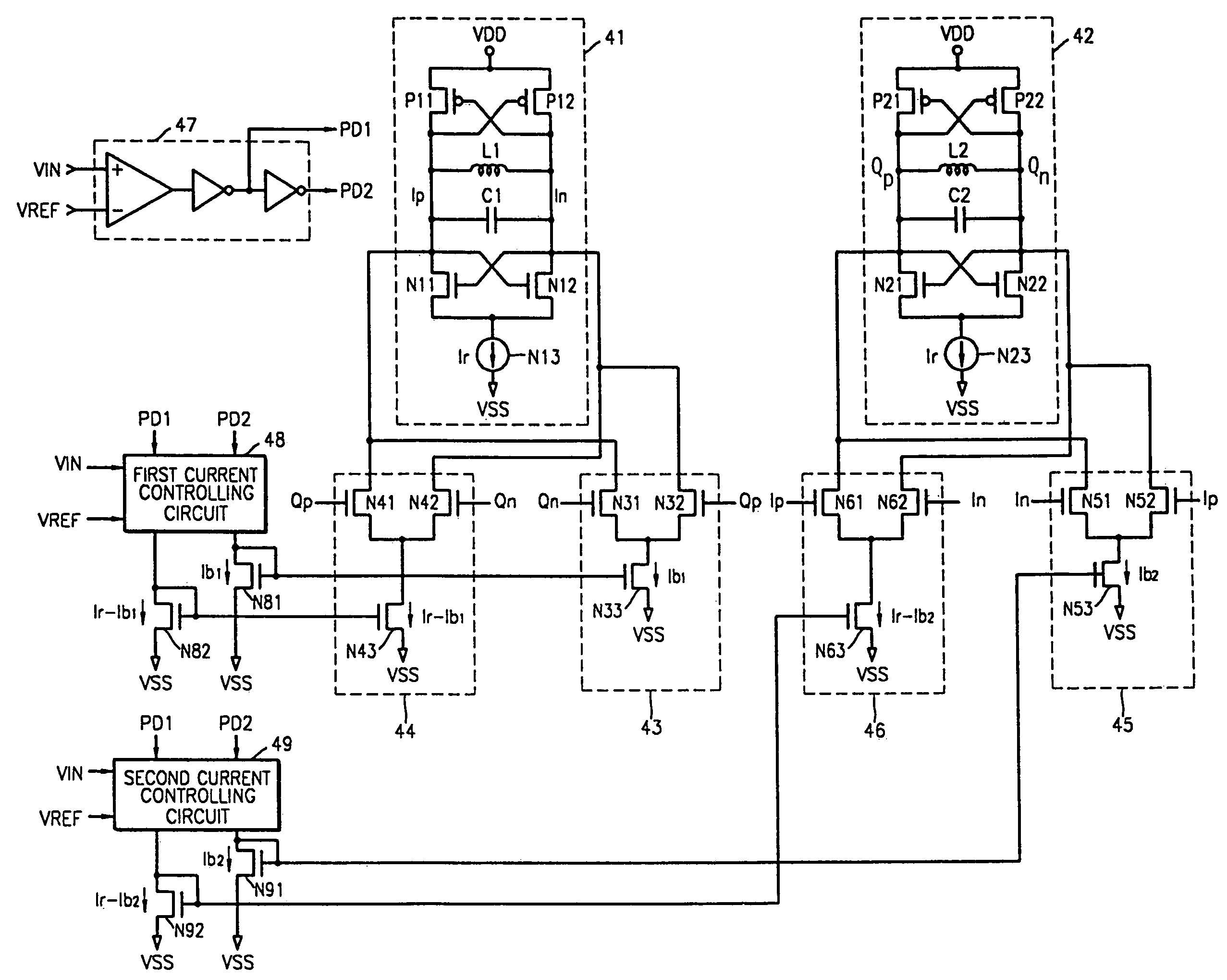
[0023]FIG. 4 shows a quadrature VCO according to an embodiment of the present invention. Referring to FIG. 4, the quadrature VCO includes a first VCO 41, a second VCO 42, a first amplifier 43, a second amplifier 44, a third amplifier 45, a fourth amplifier 46, a control signal generating circuit 47, a first current controlling circuit 48, and a second current controlling circuit 49.

[0024]The first VCO 41 generates a first output Ip and a second output In, and the second VCO 42 generates a third output Qp and a fourth output Qn. The first output Ip is a positive in-phase signal, and the second output In is a negative in-phase signal. The third output Qp is a positive quadrature signal, and the fourth output Qn is a negative quadrature signal.

[0025]The first and second VCOs 41 and 42 are general VCOs and have similar structure. The first VCO 41 includes PMOS transistors P11 and P12, an inductor L1, a capacitor C1, NMOS transistors N11 and N12, and a current source N13. The second VCO ...


PUM


Abstract

Provided is a quadrature voltage controlled oscillator capable of varying a phase difference between an in-phase output signal and a quadrature output signal. The quadrature voltage controlled oscillator comprises a first voltage controlled oscillator, a second voltage controlled oscillator, a first amplifier, a second amplifier, a third amplifier, and a fourth amplifier. The first voltage controlled oscillator generates a first output and a second output. The second voltage controlled oscillator generates a third output and a fourth output. The first output is a positive in-phase signal, and the second output is a negative in-phase signal. The third output is a positive quadrature signal, and the fourth output is a negative quadrature signal. The first amplifier is controlled by a first current and drives the first output and the second output in response to the third output and the fourth output. The second amplifier is controlled by a second current and drives the first output and the second output in response to the third output and the fourth output. The third amplifier is controlled by a third current and drives the third output and the forth output in response to the first output and the second output. The fourth amplifier is controlled by a fourth current and drives the third output and the forth output in response to the first output and the second output.

Description

BACKGROUND OF THE INVENTION[0001]1. Technical Field[0002]The present invention relates to a quadrature voltage controlled oscillator (VCO), and more particularly, to a quadrature VCO capable of varying a phase difference between an in-phase output signal and a quadrature output signal.[0003]2. Discussion of the Related Art[0004]Current mobile communication systems use low-intermediate frequency (Low-IF) way or direct-conversion way rather than heterodyne way to convert a radio frequency (RF) signal to a baseband signal. Thus, a VCO used in such mobile communication systems should generate both an in-phase output signal (I output signal) and a quadrature output signal (Q output signal).[0005]The I and Q output signals may be generated using a poly-phase-filter shown in FIG. 1, a divider shown in FIG. 2, or two VCOs shown in FIG. 3.[0006]When the I and Q output signals are generated using the poly-phase-filter as shown in FIG. 1, the poly-phase-filter is located in a path through whic...

Claims


Application Information

Patent Timeline
Patent Type & Authority Patents(United States)
IPC IPC(8): H03B27/00H03B5/00H03B5/12
CPCH03B27/00H03B5/1228H03B5/1221H03B5/1215H03B2200/0078H03B5/00
Inventor CHO, JE-KWANG
Owner SAMSUNG ELECTRONICS CO LTD
Why Eureka
Try Eureka