Discretionary dotting for artifact control in incremental printing

a technology of incremental printing and discretionary dotting, which is applied in the direction of digitally marking record carriers, visual presentation using printers, instruments, etc., can solve the problems of inability to find single insight or cure, inability to find new solutions for various banding problems, and the act of aiming one single dot into a regular grid is actually the least robust method, so as to achieve the effect of unprecedented freedom from image-quality artifacts

Inactive Publication Date: 2006-02-07
HEWLETT PACKARD DEV CO LP
View PDF12 Cites 8 Cited by
  • Summary
  • Abstract
  • Description
  • Claims
  • Application Information

AI Technical Summary

Benefits of technology

[0118]In particular, by concurrently maintaining parallel different magnitudes of colorant over such a high ran

Problems solved by technology

(a) The banding problem—White or light striations along the scan axis, often called “banding”, have been a commonly noted problem since the earliest days of incremental printing by inkjet and like printing devices, and ironically have yet to be fully resolved.
A primary reason for the seeming stubbornness of these artifacts is that several different kinds and causes of banding occur, so that no single insight or cure can be possible.
At the same time, however, new solutions for various banding problems continue to be needed because of rising quality standards and increasingly difficult operating conditions—due e.g. to marketplace demands for high throughput.
Such lines may appear singly or in clusters—since the print-element failures that produce them often occur in groups.
The act of aiming one single dot into a regular grid is actually the least robust method, as far as banding is concerned.
The chance of achieving this optimum performance, however, is small due to the loose tolerances of economical printing systems (i.e. printing elements and positioning mechanisms).
Classically, however, unfortunately each other element has its own job to do, so that actually light or white streaks due to impairment of one printing element remain discernible even though superposed upon patterns of colorant dots contributed by other elements.
The

Method used


Image

  • Discretionary dotting for artifact control in incremental printing
  • Discretionary dotting for artifact control in incremental printing
  • Discretionary dotting for artifact control in incremental printing

Examples


Embodiment Construction

1. Concurrent Plural-Drop Development

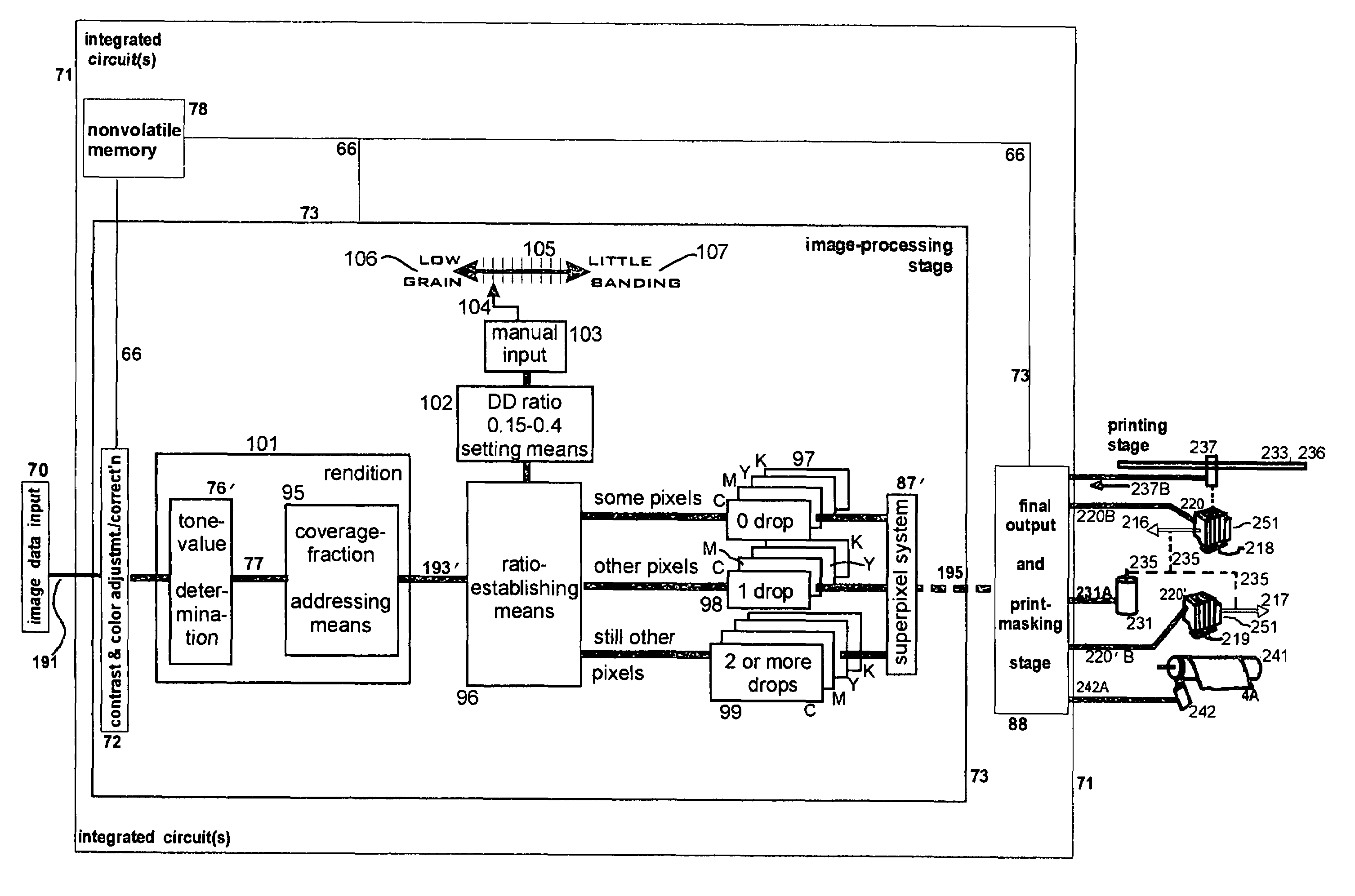
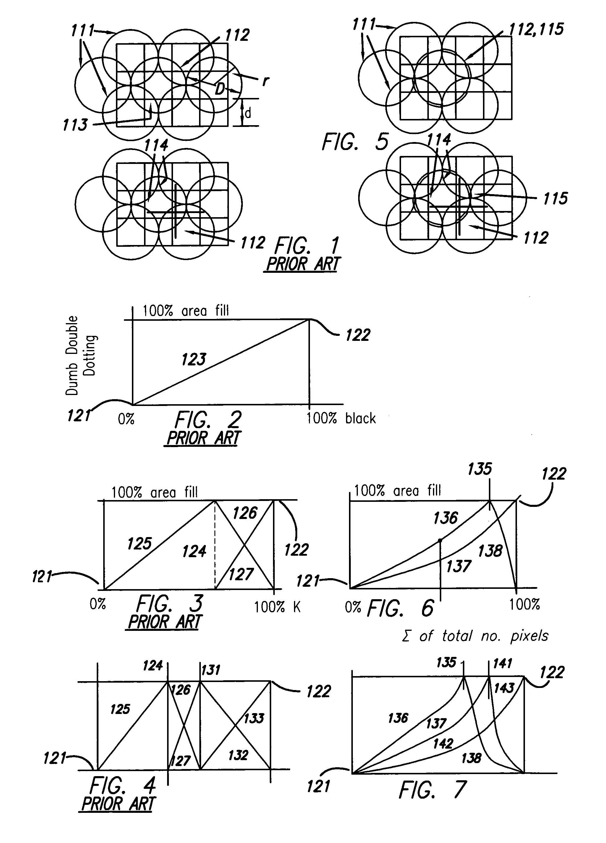
[0137]Another way to recognize the principles and practice of the invention, as introduced in the above summary section, is to see that the prior-art graphs of FIGS. 2 through 4 are no longer applicable. It is no longer true that two-drop pixel growth 127 (FIGS. 3 and 4) cannot begin until single-drop growth 125 has topped out and the system thereby reached an intermediate breakpoint 124.

[0138]Instead the number 136 (FIG. 6) of single-drop pixels and the number 137 of double-drop pixels both begin from the very smallest fractions of fill and the very finest saturations, at the origin 121. The total number of addressed pixels is the sum of the one-drop pixels 136 and two-drop pixels 137.

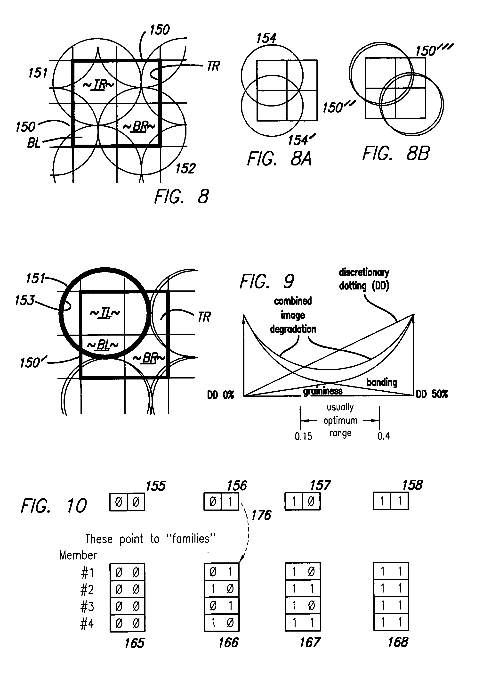
[0139]In preferred embodiments the two-drop pixel count 137 is some fraction—preferably a fixed fraction—of the single-drop count 136. The value of this fraction determines the banding / graininess tradeoff mentioned earlier, and may be set either automatically by th...


PUM


Abstract

Apparatus and method reduce banding by addressing an image region at under 100% coverage, and adding colorant quanta to selected pixels already receiving that colorant. The amount of that colorant in some pixels is zero, in others a first nonzero number of quanta, in still others a second nonzero number—different from the first. In another aspect, the invention is a method of adding colorant in a region to which colorant is already addressed; it eliminates or reduces white- or light-line banding by automatically establishing a ratio, below half, of number of added-colorant pixels to total number of addressed pixels.

Description

RELATED PATENT DOCUMENTS[0001]Closely related documents are other, coowned U.S. utility-patent applications filed in the United States Patent and Trademark Office generally contemporaneously with this document—and also hereby incorporated by reference in their entirety into this document. One is in the names of Lain et al., and entitled “RANDOMIZED SUPERPIXELS TO ENHANCE MULTILEVEL IMAGE QUALITY IN ECONOMICAL, FAST INCREMENTAL-PRINTING ERROR DIFFUSION”—and subsequently assigned utility-patent application Ser. No. 09 / 642,416. Lain is of interest for general context but especially the implementation of random selection of specific dots to be discretionarily augmented. Another such document is in the names of Garcia-Reyero et al., and entitled “IMPROVEMENTS IN AUTOMATED AND SEMIAUTOMATED PRINTMASK GENERATION FOR INCREMENTAL PRINTING”—and subsequently assigned utility-patent application Ser. No. 09 / 632,197, and issued as U.S. Pat. No. 6,443,556. The Garcia-Reyero document and others cit...

Claims


Application Information

Patent Timeline
IPC IPC(8): G06F15/00G06F13/00
CPCG06K15/02H04N1/4015H04N1/40087
Inventor MIGUEL, ANTONI GIL
Owner HEWLETT PACKARD DEV CO LP
Why Eureka
Try Eureka