Low visibility watermark using time decay fluorescence
What is AI technical title?
AI technical title is built by Patsnap AI team. It summarizes the technical point description of the patent document.
a fluorescence and low-visibility technology, applied in the field of digital watermarks, can solve the problems of not being as easy to spot pirates as they used, affecting the quality of counterfeit products,
Inactive Publication Date: 2006-02-07
DIGIMARC CORP
View PDF32 Cites 216 Cited by
Summary
Abstract
Description
Claims
Application Information
AI Technical Summary
This helps you quickly interpret patents by identifying the three key elements:
Problems solved by technology
Method used
Benefits of technology
Problems solved by technology
It's not as easy to spot a pirate as it used to be.
They remain common thieves.
Consumers increasingly face the difficult task of discerning genuine products from counterfeits and pirated copies.
A fragile watermark is designed to be lost, or to degrade predictably, when the data set into which it is embedded is processed in some manner, such as signal processing, compression scanning / printing, etc.
A watermark may be made fragile in numerous ways.
If any significant fraction of the signal is lost, as typically occurs in photocopying operations, the watermark becomes unreadable.
Even a high amplitude watermark signal can be significantly impaired, and rendered unreadable, by such photocopying operations.
Method used
Image
Click on the blue label to locate the original text in one second.
Reading with bidirectional positioning of images and text.
Examples
Embodiment Construction
Introduction
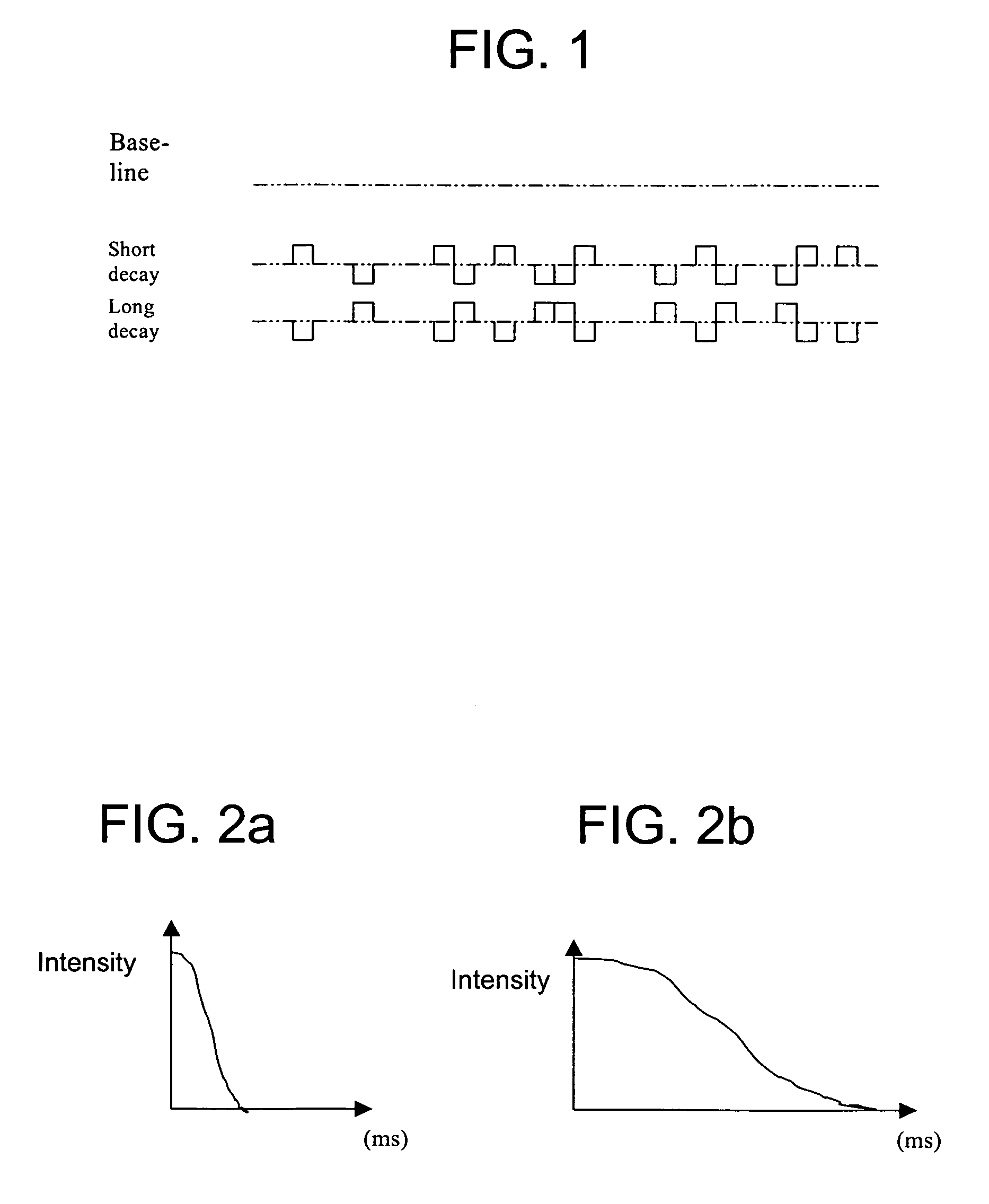
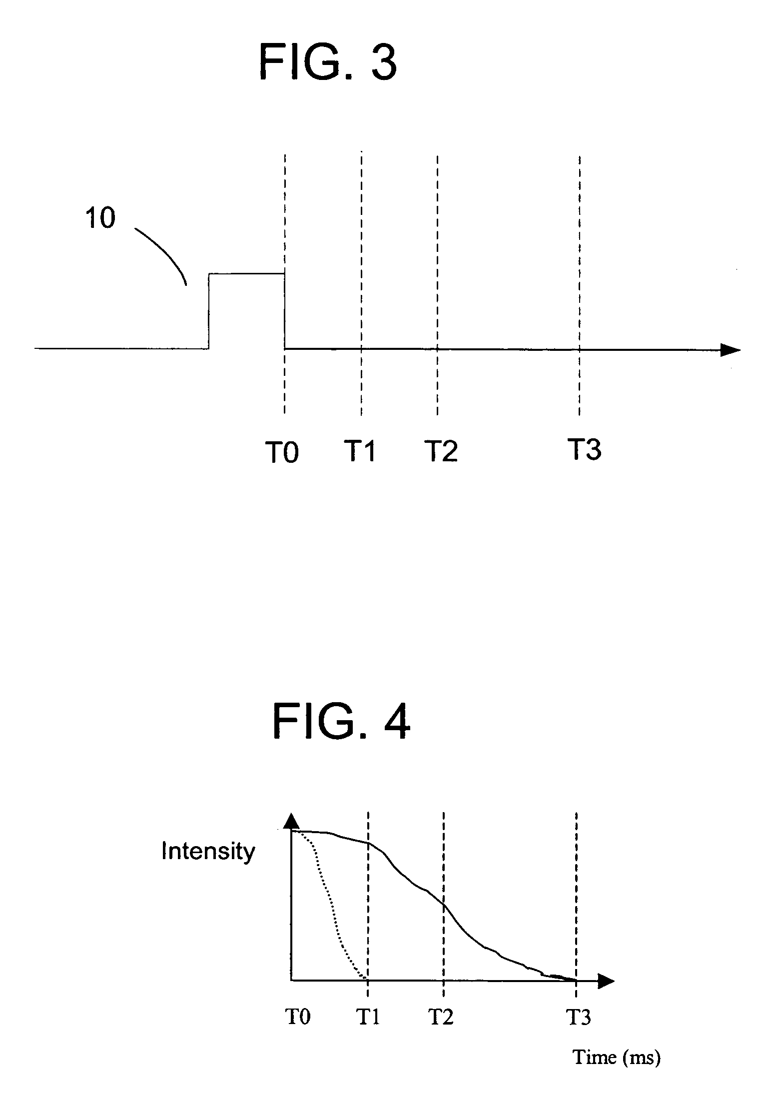
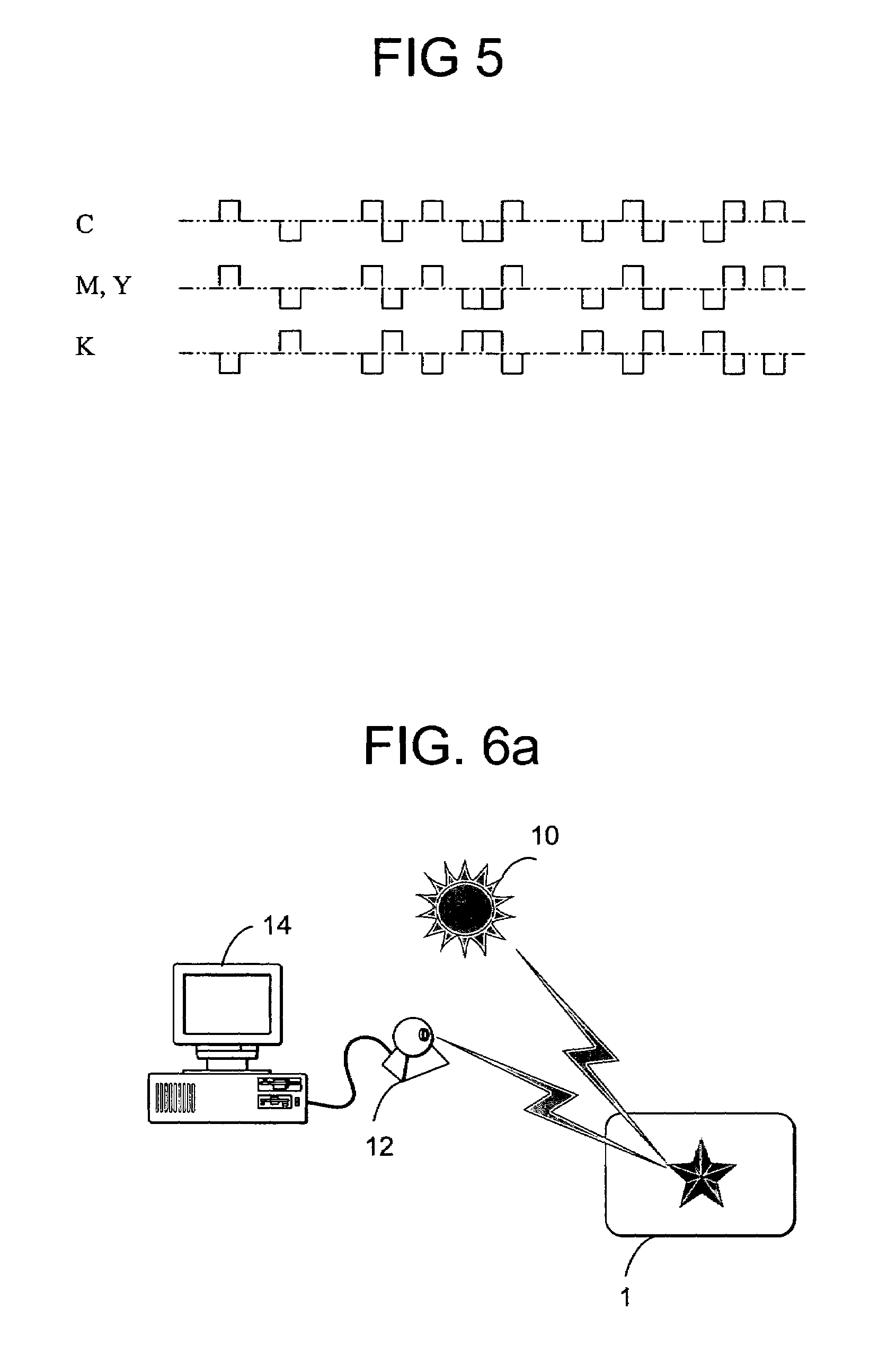
[0026]Inks and dyes have recently emerged with unique fluorescent properties. Some of these properties allow for variable fluorescence (or emission) decay times. Typical decay times can be varied from less than a microsecond to tens of milliseconds and more. A CCD scanner and microprocessor can measure the decay emissions from the inks and dyes. Other filtered optical capture devices (cameras, digital cameras, web cameras, etc.) can be suitably interchanged with the CCD scanner. These inks and dyes (both hereafter referred to as “ink”) also include unique emission characteristics, such as emitting in a particular frequency band, which allows for frequency-based detection. Other unique characteristics include varying the frequency of light needed to activate the ink and the color of the ink's fluorescence. These characteristics can be variously combined to produce customized ink. These types of ink are typically excited with UV light and emit from ultraviolet (UV) to infr...
PUM
Abstract
A physical object is embedded with a first digital watermark component and a second digital watermark component. The first component is printed using a first ultraviolet (UV) ink. The first UV ink includes a first fluorescence decay time. The second component is printed using a second UV ink. The second ink includes a second fluorescence decay time, which is longer than the first decay time. The embedded media is illuminated with a UV pulse. The first component is detected after the first emission decay time, but before the second emission decay time.
Description
RELATED APPLICATION DATA[0001]This application is a continuation of U.S. patent application Ser. No. 09 / 945,243 (U.S. Pat. No. 6,718,046) filed Aug. 31, 2001 now U.S. Pat. No. 6,718,046, which is a continuation in part of U.S. patent application Ser. No. 09 / 933,863 (U.S. Pat. No. 6,763,123), filed Aug. 20, 2001, which is a continuation in part of U.S. patent application Ser. No. 09 / 898,901 (U.S. Pat. No. 6,721,440), filed Jul. 2, 2001, which is a continuation in part of U.S. patent application Ser No. 09 / 553,084 (U.S. Pat. No. 6,590,996), filed Apr. 19, 2000. The present application is also related to U.S. patent application Ser. No. 09 / 503,881 (U.S. Pat. No. 6,614,914), filed Feb. 14, 2000, which is a continuation in part of application Ser. No. 09 / 186,962, filed Nov. 5, 1998, which is a continuation of application Ser. No. 08 / 649,419, filed May 16, 1996, now U.S. Pat. No. 5,862,260; application Ser. No. 08 / 649,419 is a continuation in part of PCT / US96 / 06618, filed May 7, 1996, U.S...
Claims
Application Information
Patent Timeline
Application Date:The date an application was filed.
Publication Date:The date a patent or application was officially published.
First Publication Date:The earliest publication date of a patent with the same application number.
Issue Date:Publication date of the patent grant document.
PCT Entry Date:The Entry date of PCT National Phase.
Estimated Expiry Date:The statutory expiry date of a patent right according to the Patent Law, and it is the longest term of protection that the patent right can achieve without the termination of the patent right due to other reasons(Term extension factor has been taken into account ).
Invalid Date:Actual expiry date is based on effective date or publication date of legal transaction data of invalid patent.

