Systems and methods for measurement of low liquid flow rates

a technology of liquid flow rate and measurement system, which is applied in the direction of volume metering, machines/engines, instruments, etc., can solve the problems of unreliable measurement, low accuracy, and inability to easily control the droplet size or flow rate of users, etc., and achieves low manufacturing cost, simple, rugged

Inactive Publication Date: 2006-02-14
AIR LIQUIDE ELECTRONICS US LP
View PDF1 Cites 29 Cited by
  • Summary
  • Abstract
  • Description
  • Claims
  • Application Information

AI Technical Summary

Benefits of technology

[0006]In another feature, liquid is supplied and after a hydraulic stabilization period, the controller captures a load cell signal and opens a timing window. At the end of the timing window the controller captures another load cell signal. The controller calculates the mass of the collected liquid over the collection period and the flow rate such as mass rate and / or the volumetric rate. The duration of the timing window depends on the measurement desired. Since the liquid wells up and overflows the weir, the system can make precise measurements of low flow rates.
[0008]The liquid flow rate measurement systems and methods are sensitive and well suited to measure low flow rates. The systems and methods can scale, if desired, to measure a wide range of liquid flow rates including a range of viscosities. The liquid flow rate system is simple, rugged, and low cost to manufacture, and relatively immune to environmental change and minor physical perturbation.

Problems solved by technology

As the desired accuracy approaches the droplet volume, measurements become unreliable.
The reaction cell 16 senses the impact of the droplet, but the user cannot readily control the droplet size or flow rate and the measurements are susceptible to environmental change and minor physical perturbations.
Sampling of a droplet is also inaccurate if the droplet forms at the funnel opening due to surface tension or falls in mid-air before impact between measurement intervals.
This method is also unsuitable for measuring higher liquid flow rates not forming droplets, thus limiting its applications.
Those methods are not suitable for very low flow rate measurements where error tolerances exceed the droplet or sub-droplet range.
Floatation devices have delicate mechanical parts prone to calibration errors and physical damage, adding to manufacturing and maintenance costs.

Method used


Image

  • Systems and methods for measurement of low liquid flow rates
  • Systems and methods for measurement of low liquid flow rates
  • Systems and methods for measurement of low liquid flow rates

Examples


Embodiment Construction

[0016]The following description includes the best mode of carrying out the invention. The detailed description is made for the purpose of illustrating the general principles of the invention and should not be taken in a limiting sense. The scope of the invention is determined by reference to the claims.

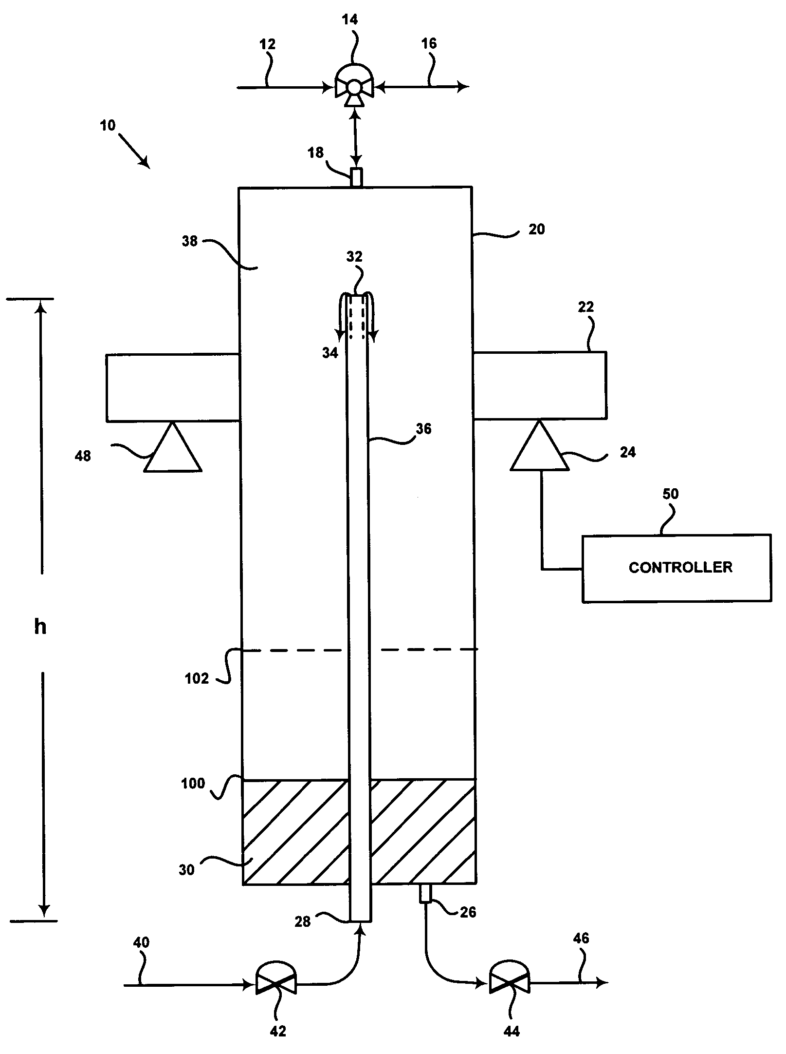
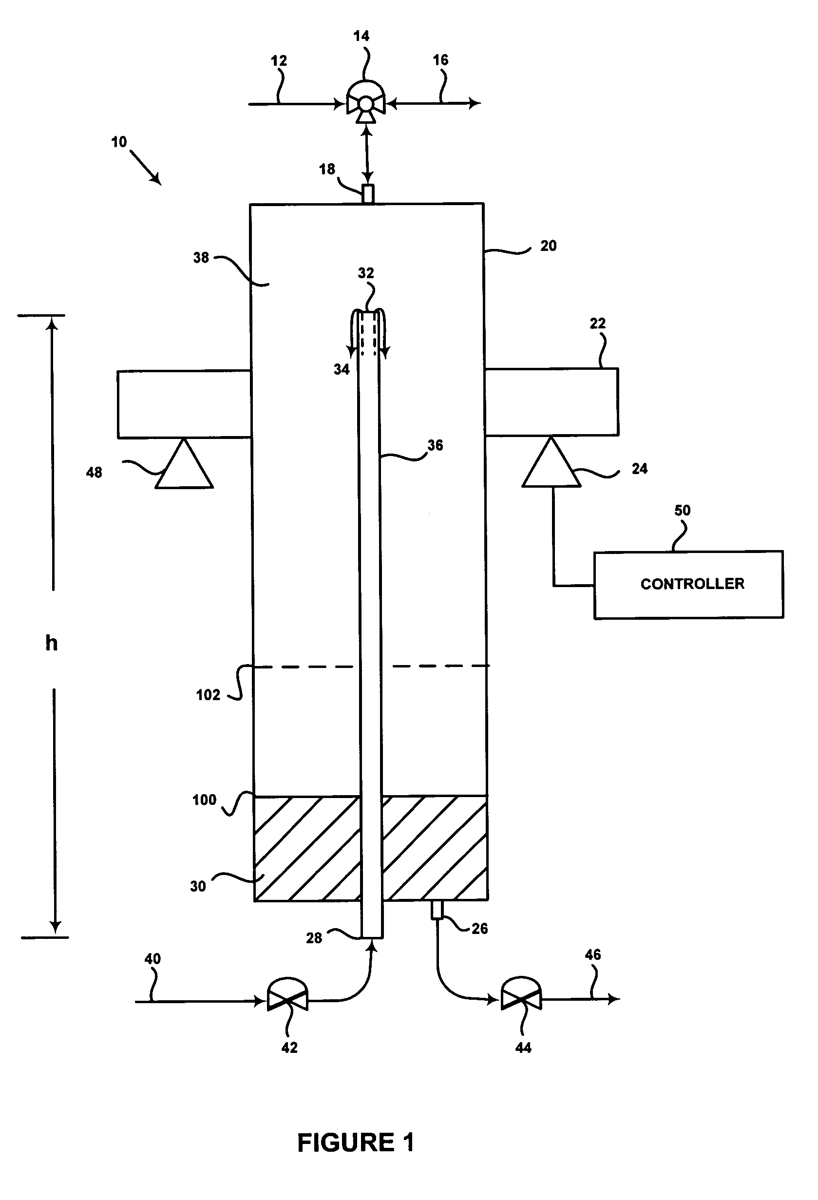
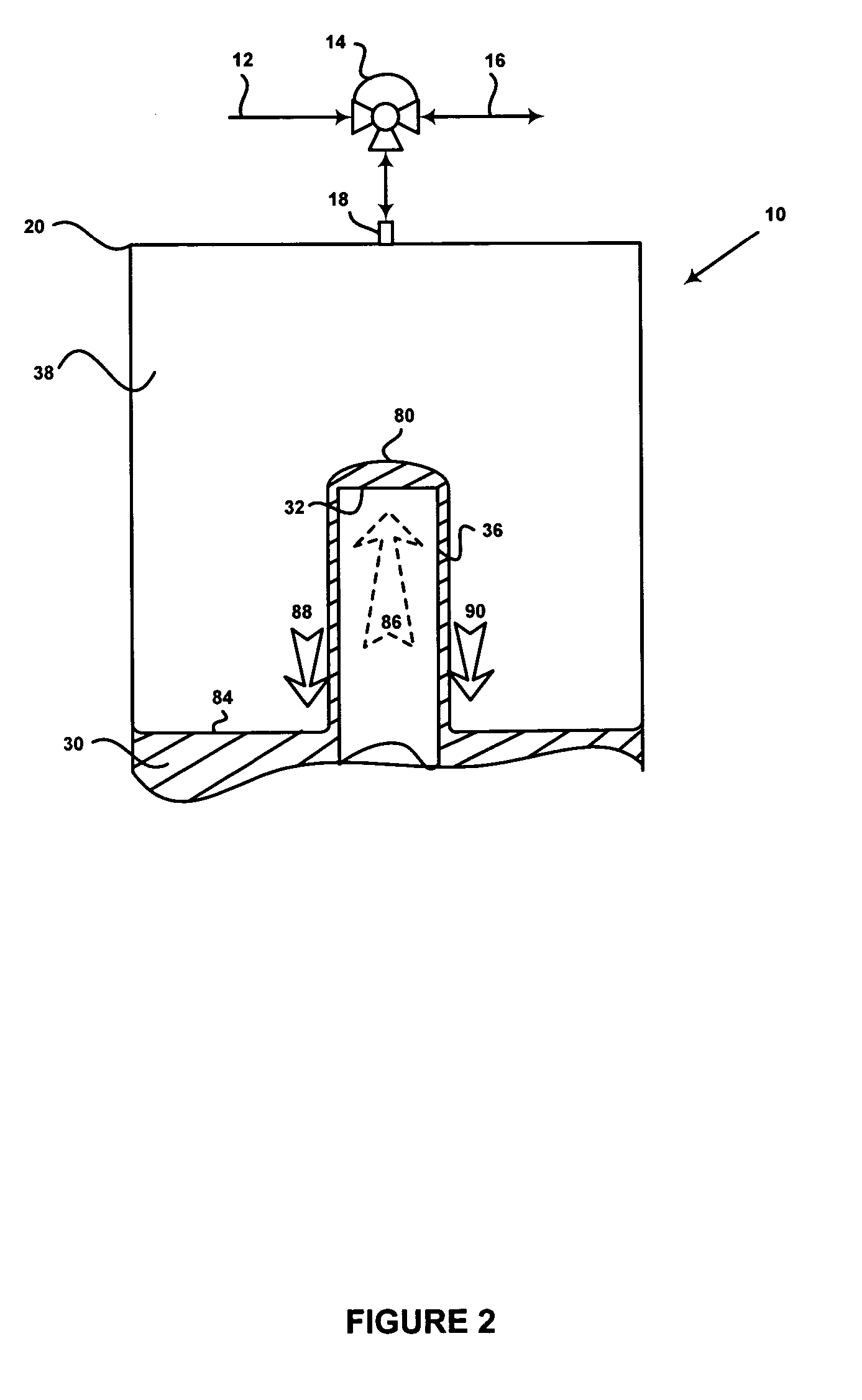
[0017]FIG. 1 illustrates an embodiment of a system for low liquid flow rate measurement. The system 10 includes a weir 36 disposed in a collection vessel 20. The weir 36 of height h provides a passage for liquid supplied from a liquid supply inlet 28 to a weir opening 32 disposed above the floor of the collection vessel 20. It is not essential that the bottom of the weir 36 extend beyond the bottom of the collection vessel 20 as depicted. It could also extend from the bottom of the collection vessel 20. The collection vessel 20 and the weir 36 are preferably made of a light weight material with low surface tension and chemically non-reactive and / or corrosion resistant with respect to ...


PUM


Abstract

The invention relates to systems and methods of measuring low liquid flow rates. The system provides a controller, flow system components, and one or more load cells coupled to a collection vessel. The collection vessel includes a weir that serves as a passage to allow liquid to rise within the weir until the liquid overflows the weir. After the liquid supplied passes a hydraulic stabilization period the controller captures a load cell signal and opens a timing window. At the end of the timing window the controller captures another load cell signal. A controller calculates the mass of the collected liquid over the collection period and the flow rate such as mass rate and / or the volumetric rate. The duration of the timing window depends on the measurement desired. Since the liquid wells up and overflows the weir, the system can make precise measurements of low flow rates. In another feature, feedback control mechanisms are implemented in the batch constant flow method or steady state constant flow method. In both methods, the instantaneous measured flow rate is compared with an input command derived from flow rate calibration, sending an error correction feedback signal to the controlled valves to actuate the flow rate of liquid supply and the drain and the gas pressure, until zero error or an acceptable error margin is reached or the desired flow rate is established.

Description

BACKGROUND[0001]The present invention relates to the measurement of liquid flow rates.[0002]Semiconductor manufacturers, the health industry, the food industry and others require accurate measurement of low liquid flow rates. Low liquid flow rates tend to break up into a series of droplets of small volume. As the desired accuracy approaches the droplet volume, measurements become unreliable.[0003]U.S. Pat. No. 4,869,722 describes a device that tries to address this problem by monitoring the droplets released from the tip of a drop funnel 13 onto a liquid at the top of a reaction cell 16. The reaction cell 16 senses the impact of the droplet, but the user cannot readily control the droplet size or flow rate and the measurements are susceptible to environmental change and minor physical perturbations. The droplet size cannot change without altering the funnel opening diameter, and the liquid flow rate changes with variations in liquid supply height. Sampling of a droplet is also inacc...

Claims


Application Information

Patent Timeline
Patent Type & Authority Patents(United States)
IPC IPC(8): G01F23/20G01F1/52G01F1/00G01F13/00
CPCG01F13/00G01F1/007G01F1/52G01F23/20
Inventor FORSHEY, RANDY G.POZNIAK, PETER M.
Owner AIR LIQUIDE ELECTRONICS US LP
Why Eureka
Try Eureka