Circular saw

a circular saw and saw blade technology, applied in the field of circular saws, can solve the problems of affecting the operation of the saw unit, affecting the workpiece, and consuming time, and achieve the effect of smooth and easy cutting operation

Inactive Publication Date: 2006-02-14
MAKITA CORP
View PDF11 Cites 46 Cited by
  • Summary
  • Abstract
  • Description
  • Claims
  • Application Information

AI Technical Summary

Benefits of technology

[0017]If the second lock device is provided, the operator can perform a cutting operation while the saw unit is moved in the horizontal direction, with

Problems solved by technology

However, manually tightening a fixing bolt to fix the horizontal position of the saw unit every time that a cutting operation is performed or every time after the miter saw unit is set at an appropriate horizontal position above the workpiece is both troublesome and time consuming.
As a result, circular saws of this type possess a substantial hindrance in operability.
In order to counteract this reaction force, the opera

Method used


Image

  • Circular saw
  • Circular saw
  • Circular saw

Examples


Embodiment Construction

[0032]A first representative embodiment of the present invention will now be described with reference to FIGS. 1 to 6.

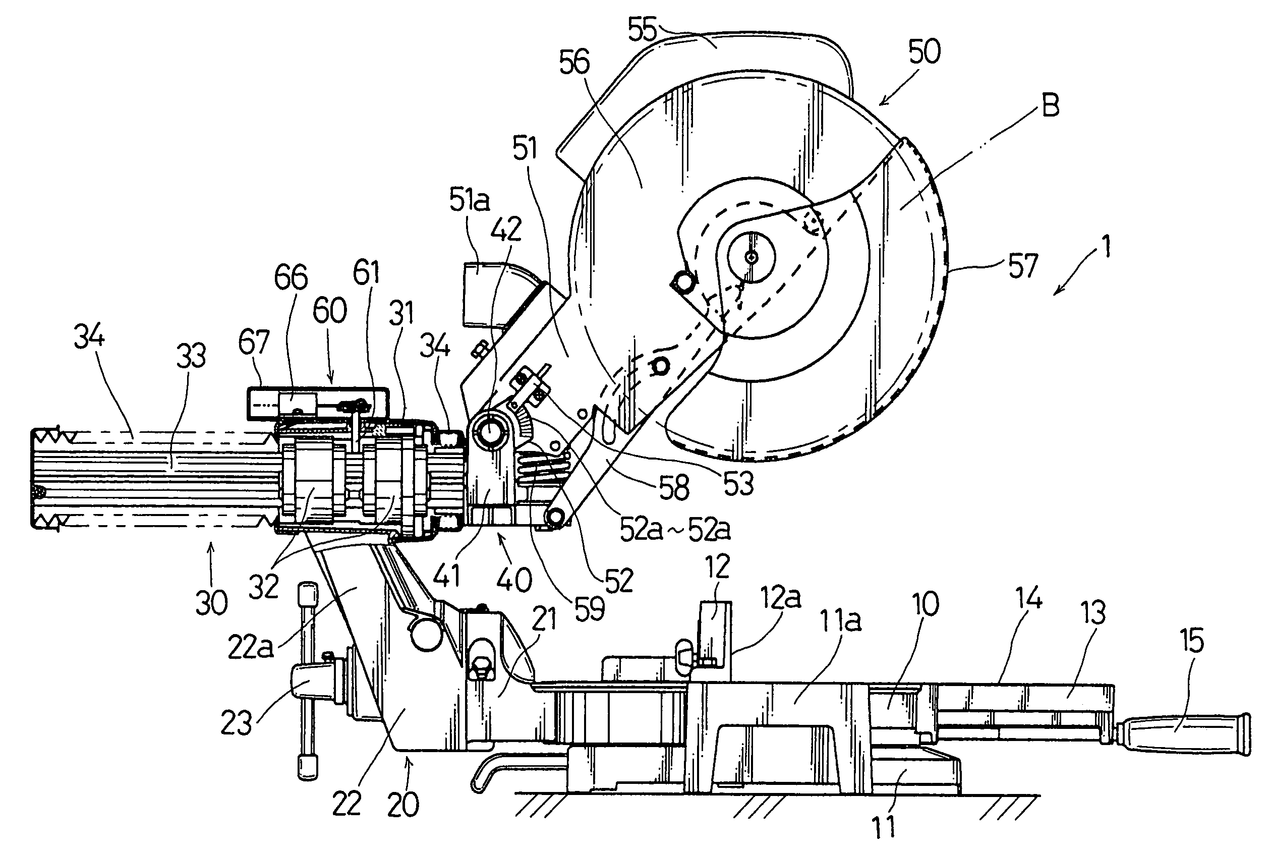
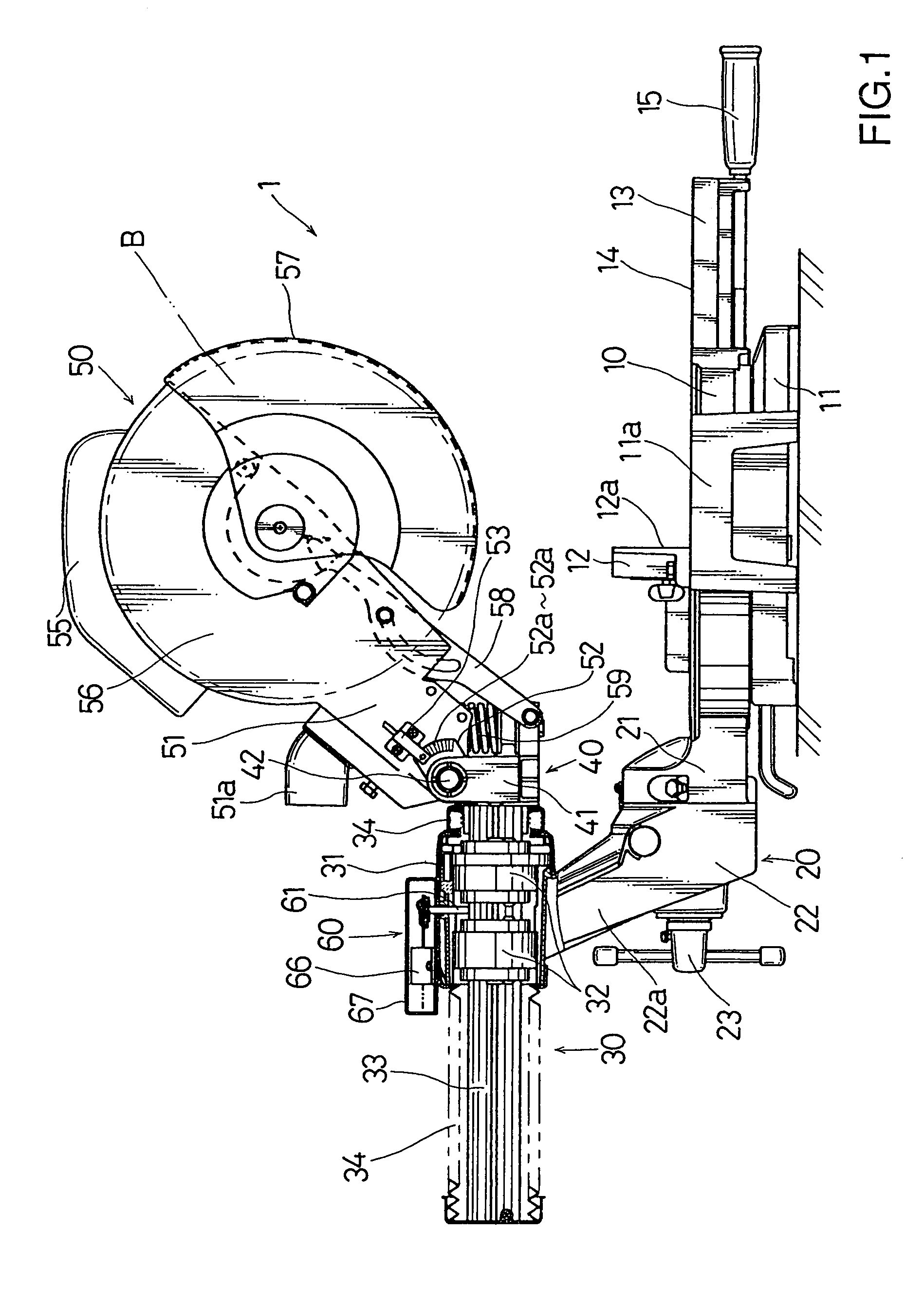
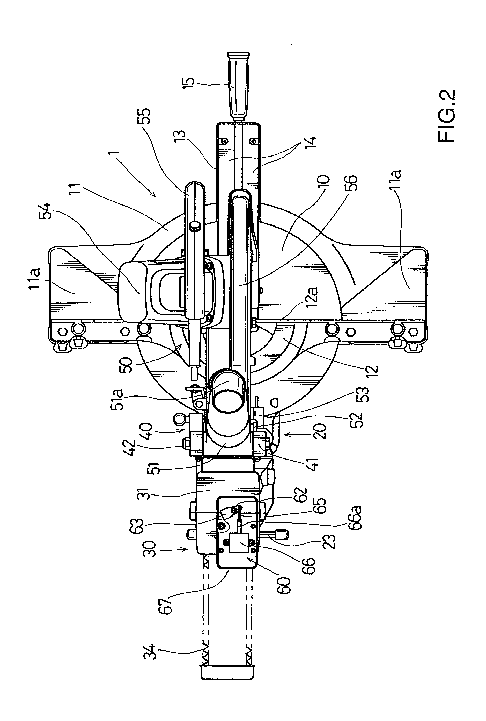
[0033]A circular saw 1 is generally shown in FIGS. 1 and 2 and includes a table 10 for placing a workpiece (not shown) thereon. A saw unit 50 is mounted on the table 10 by means of a support device including a lateral pivot mechanism 20, a horizontal slide mechanism 30, and a vertical hinge mechanism 40. The lateral pivot mechanism 20 is disposed at the rear portion (left side portion as viewed in FIG. 1) of the table 10. The slide mechanism 30 is disposed above the lateral pivot mechanism 20. The saw unit 50 is mounted on the front side (right side as viewed in FIG. 1) of the slide mechanism 30 by means of the vertical hinge mechanism 40.

[0034]The construction of the table 10 and the lateral pivot mechanism 20 will now be briefly described. The table 10 is rotatably mounted on a base 11. The base 11 includes a pair of auxiliary tables 11a disposed on both lateral si...


PUM

PropertyMeasurementUnit
Distanceaaaaaaaaaa
Mechanical energyaaaaaaaaaa

Abstract

A circular saw includes a table having an upper surface for placing a workpiece thereon. A saw unit has a saw blade mounted thereon and is supported on the table such that the saw unit is movable in a horizontal direction parallel to the upper surface of the table and is movable in a vertical direction perpendicular to the upper surface of the table. At least one of a first lock device and a second lock device is provided. The first lock device is operable to prevent the saw unit from moving in the horizontal direction in response to the movement of the saw unit in the vertical direction. The second lock device is operable to prevent the saw unit from moving in the vertical direction in response to the movement of the saw unit in the horizontal direction.

Description

FIELD OF THE INVENTION[0001]The present invention relates to circular saws, such as miter saws, which have a table for placing thereon a workpiece to be cut, and which have a saw unit that includes a saw blade and that is horizontally and vertically movable relative to the table.DESCRIPTION OF THE RELATED ART[0002]In circular saws of this type, when a workpiece is to be cut by lowering a saw unit toward a table or when a cutting operation known as a chopping operation or a miter cutting operation is performed, the position of the saw unit in the horizontal direction preferably should be fixed by using a fixing device, such as a fixing bolt disclosed in U.S. Pat. No. 5,437,214.[0003]However, manually tightening a fixing bolt to fix the horizontal position of the saw unit every time that a cutting operation is performed or every time after the miter saw unit is set at an appropriate horizontal position above the workpiece is both troublesome and time consuming. As a result, circular s...

Claims


Application Information

Patent Timeline
IPC IPC(8): B27B5/20B23D45/02B23D45/04B23D59/00
CPCB23D59/001B23D45/048Y10T83/626Y10T83/7697Y10T83/7763Y10T83/7772Y10T83/7788
Inventor SHIBATA, YOSHINORI
Owner MAKITA CORP
Why Eureka
Try Eureka