
Pressure Compensating valve

a pressure compensating valve and valve body technology, applied in the direction of diaphragm valves, engines, instruments, etc., can solve the problems of complex, difficult manufacturing and service, and relatively expensive existing balanced pressure compensating valves, and achieve significant manufacturing and cost advantages

Inactive Publication Date: 2006-02-14
SAFETY EQUIP SWEDEN AB
View PDF12 Cites 21 Cited by
  • Summary
  • Abstract
  • Description
  • Claims
  • Application Information

AI Technical Summary

Benefits of technology

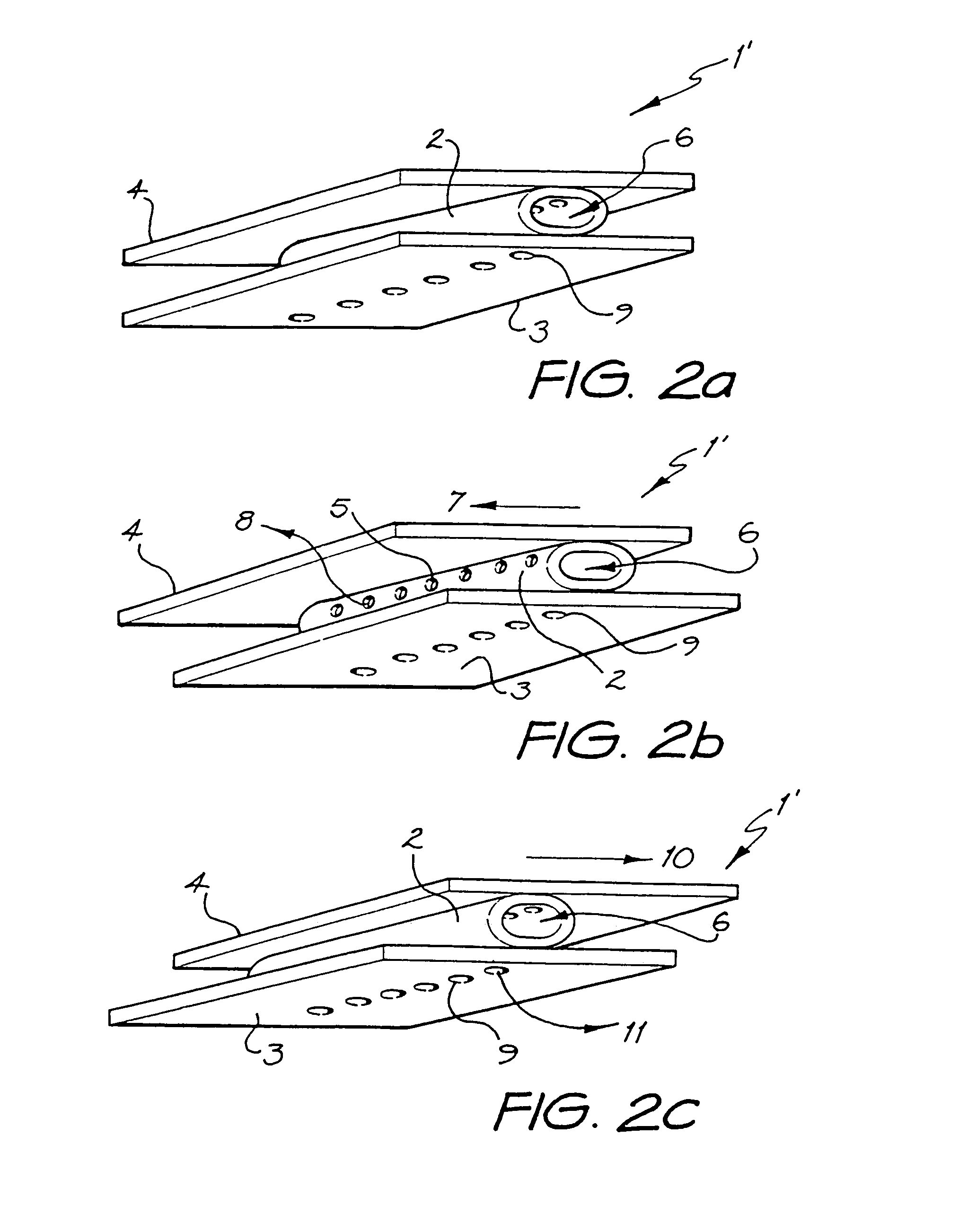
[0010]The valve may further comprise an exhaust aperture in one of the first or second surfaces, which is selectively occluded by the flexible barrier in the first and second positions, but open in a third position. In the third position the fluid outlet is occluded. In this way the valve may control both the supply and exhaust of the fluid supply.
[0018]The first and second surfaces may be conveniently formed by injection moulding of a synthetic plastics material, and the flexible barrier may be formed of a suitably flexible rubber or synthetic plastics material. As the valve may be made from only few pieces, and from relatively cheap materials, it can be seen that it may offer significant manufacturing and cost advantages over known pressure compensating valves.

Problems solved by technology

Existing balanced pressure compensating valves are relatively expensive, complex and difficult to manufacture and service.

Method used


Image

  • Pressure Compensating valve
  • Pressure Compensating valve
  • Pressure Compensating valve

Examples


Embodiment Construction

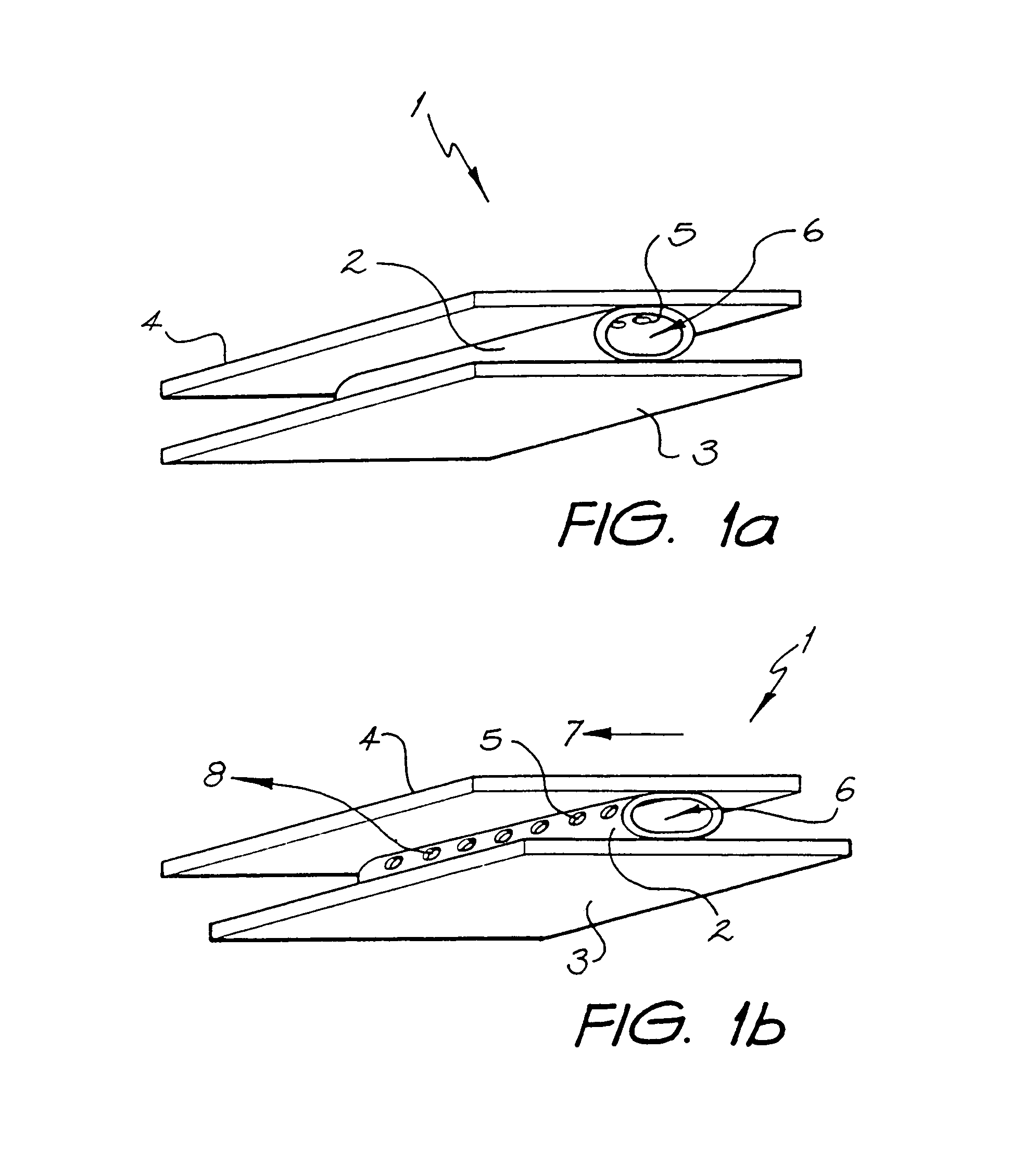
[0033]FIG. 1a shows a pressure compensating valve 1 comprising a tube of flexible material 2 trapped between a first planar surface 3 and a second planar service 4.

[0034]A series of holes 5 extending along the upper side of the flexible tube 2 penetrate through its walls. The tube 2 itself defines a chamber 6 into which fluid is pumped, from a source which is not shown. In the position shown in FIG. 1a the fluid cannot escape from the chamber 6 but remains there at supply pressure.

[0035]When the upper planar surface 4 moves to the left with respect to the lower planar surface 3, as indicated by arrow 7 in FIG. 1b, the line of holes 5 are rotated anti-clockwise as friction between the tube 2 and the planar members causes it to roll between the planar surfaces. Once the holes clear the upper planar surface 4, fluid may flow through holes 5 from the relatively high pressure within chamber 6 to the relatively low pressure area indicated at the end of arrow 8.

[0036]If a reference pressur...


PUM


Abstract

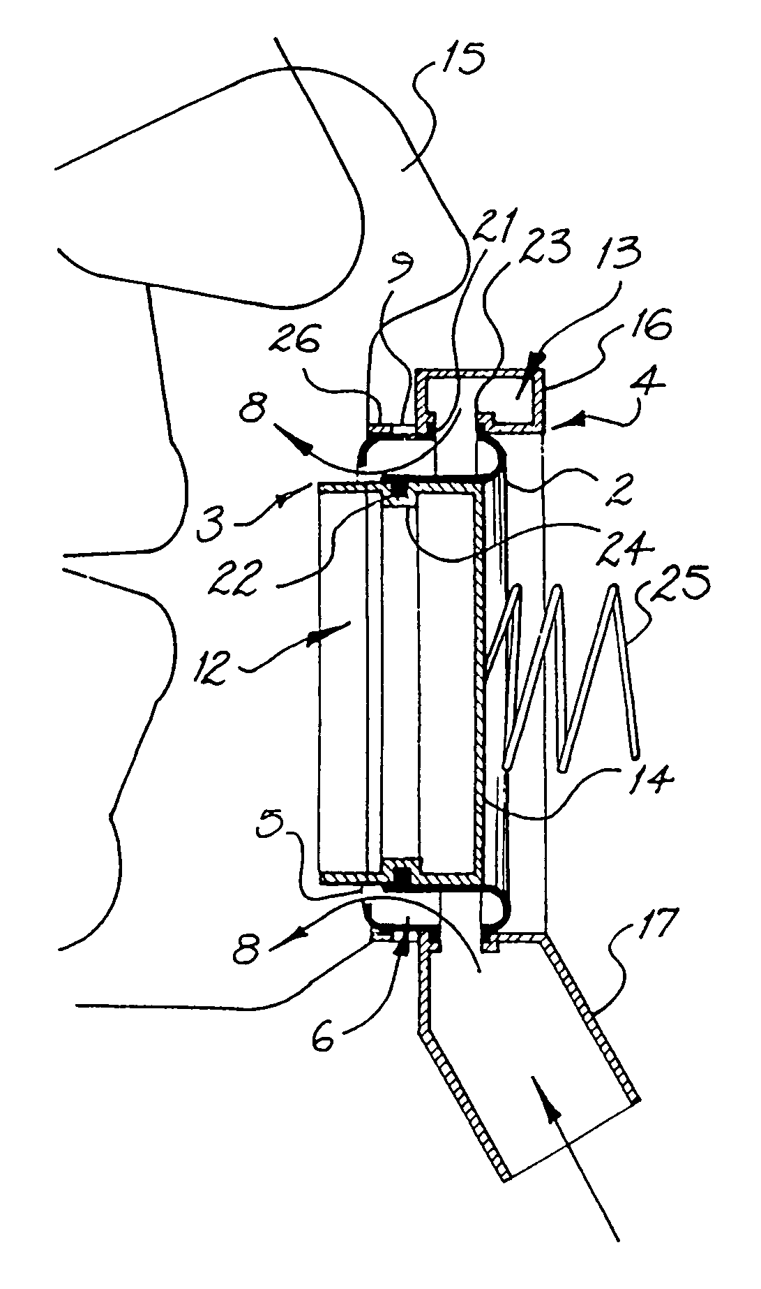
This invention relates to a pressure compensating valve and more particularly, but not exclusively, to a balanced pressure compensating valve, or regulator. The valve includes a chamber (6) for containing fluid, defined by a flexible barrier (2) trapped between first (3) and second (4) surfaces. A fluid inlet provides fluid to the interior of the chamber. A fluid outlet selectively allows fluid to pass out of the chamber. Movement of the first (3) and second (4) surfaces relative to each other causes change in contact between the flexible barrier and the first and second surfaces to selectively open the fluid outlet, in a first position, and occlude it between the flexible barrier and one of the surfaces, in a second position.

Description

FIELD OF THE INVENTION[0001]The present invention relates to a pressure compensating valve and more particularly, but not exclusively, to a balanced pressure compensating valve, or regulator.BACKGROUND ART[0002]Pressure compensating valves are widely used in the supply of gases and liquids from a high pressure supply to a low pressure user. It is often desirable to maintain the low pressure side of the valve at a substantially constant pressure irrespective of pressure fluctuations on the high pressure side of the valve. Balanced pressure compensating valves are known for this purpose.[0003]Existing balanced pressure compensating valves are relatively expensive, complex and difficult to manufacture and service. The present invention is directed to a pressure compensating valve which can, at least in preferred embodiments, be made in a very simple form at low cost and with good performance characteristics.SUMMARY OF THE INVENTION[0004]The invention is a pressure compensating valve in...

Claims


Application Information

Patent Timeline
IPC IPC(8): F16K7/18A62B18/10A62B9/02F16K7/02
CPCA62B18/10F16K7/02F16K7/18Y10S251/901Y10S137/908Y10T137/7842Y10T137/2544Y10T137/784F16K2200/301
Inventor KLOCKSETH, MARTINUS OLIVERJERVMO ROLAND, BENGT YNGVEBERNDTSSON, GORAN BERTIL CLAES
Owner SAFETY EQUIP SWEDEN AB
Learn More