Reflective liquid crystal projector

a liquid crystal projector and projector technology, applied in the field of reflective liquid crystal projectors, can solve problems such as deteriorating image quality, and achieve the effect of saving mounting space and being more compa

Inactive Publication Date: 2006-02-14
FUJI PHOTO OPTICAL CO LTD
View PDF5 Cites 1 Cited by
  • Summary
  • Abstract
  • Description
  • Claims
  • Application Information

AI Technical Summary

Benefits of technology

[0005]In view of the foregoing, a primary object of the present invention is to provide a reflective liquid crystal projector that is compact and achieves a high quality of the projected image.
[0008]As shown in FIG. 1, the polarizing beam splitters 8, 10 are fixed merely at their bottom surfaces to the prism base plate and are not fixed to a support at their top surfaces. Therefore, if the prism base plate swells thermally, the polarizing beam splitters will not lean, so the image projected on the screen will not be deteriorated. Moreover, because it is unnecessary to bond some prism holders on the top and the bottom sides of the PBS prisms, this configuration saves the mounting space, so the reflective liquid crystal projector of the present invention can be made more compact.

Problems solved by technology

Because of thermal swelling of the prism holders, which is caused while the liquid crystal projector is being used, the PBS prism leans to distort the image projected on the screen, deteriorating the image quality.

Method used


Image

  • Reflective liquid crystal projector
  • Reflective liquid crystal projector
  • Reflective liquid crystal projector

Examples


Embodiment Construction

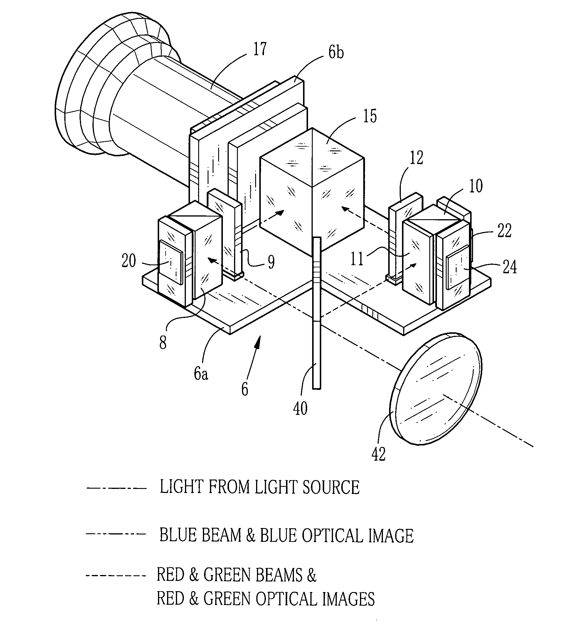
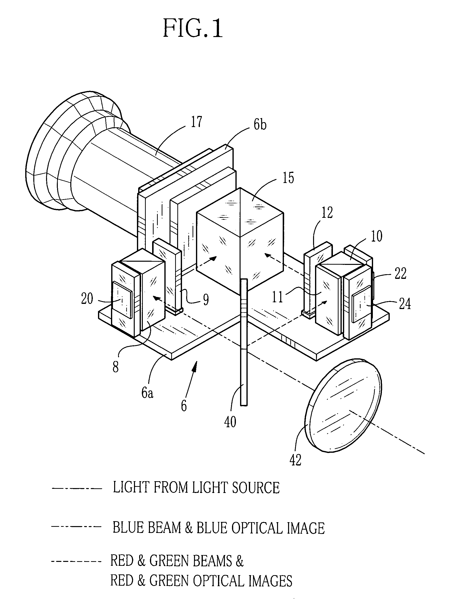
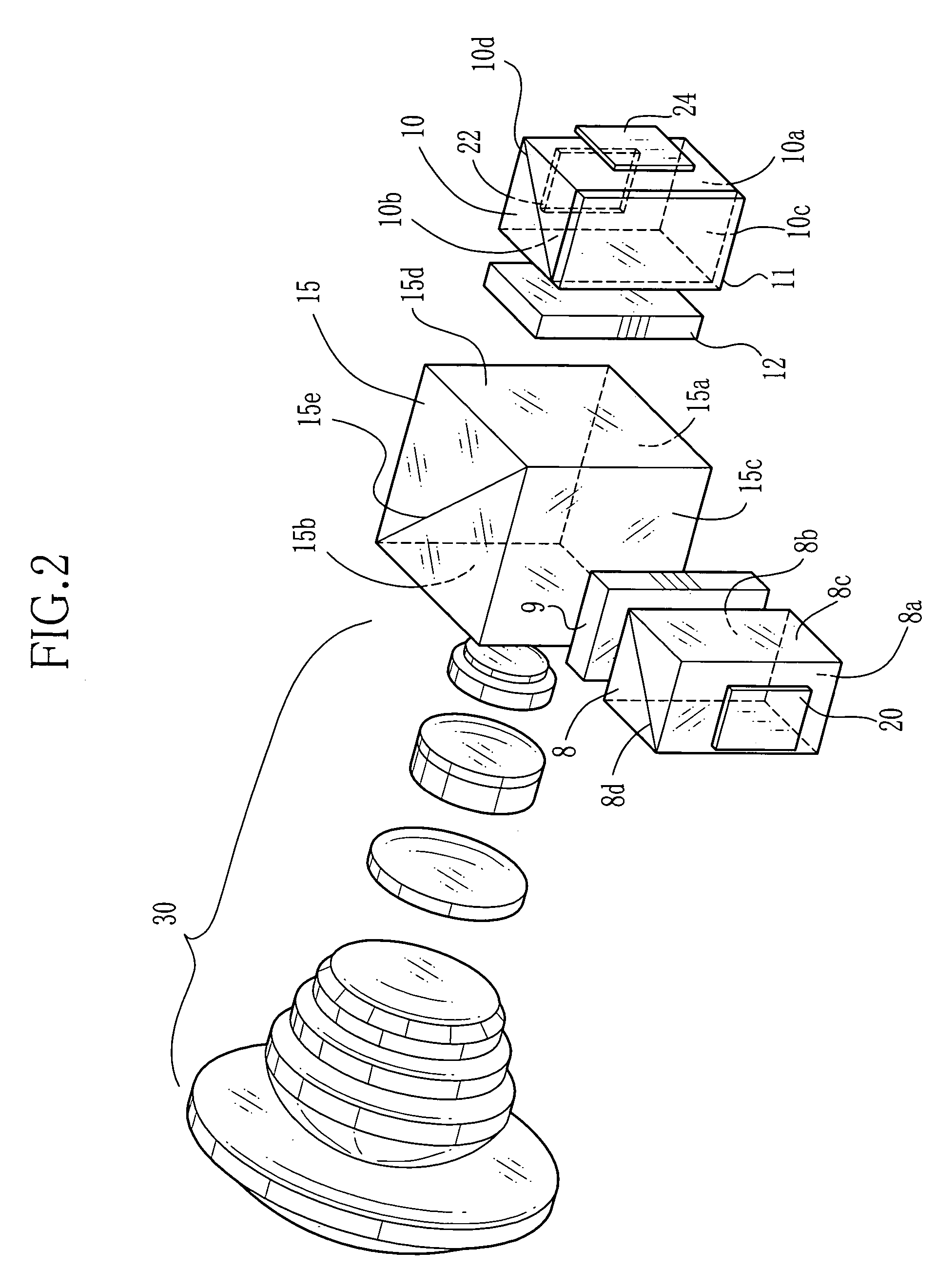
[0015]In FIG. 1, a base frame 6 consists of a prism base plate 6a and a lens mounting plate 6b. The prism base plate 6a holds first and second PBS prisms 8 and 10 of a rectangular prism shape, a recombination prism 15, and first to third polarization rotators 9, 11 and 12 thereon.

[0016]A reflective liquid crystal element 20 for modulating blue illumination light is disposed in opposition to a side surface of the first PBS prism 8, and the first PBS prism 8 separates the light path of the blue optical image that is modulated through the liquid crystal element 20, from the light path of the blue illumination light.

[0017]A reflective liquid crystal element 22 for modulating red illumination light and a reflective liquid crystal element 24 for modulating green illumination light are disposed in opposition to first and second side surfaces of the second PBS prism 10. The second PBS prism 10 separates the light path of the red optical image that is modulated through the liquid crystal ele...


PUM

PropertyMeasurementUnit
colorsaaaaaaaaaa
coloraaaaaaaaaa
opticalaaaaaaaaaa

Abstract

In a reflective liquid crystal projector, illumination light is separated into blue, green and red illumination light bundles. The three color illumination light bundles are respectively modulated through three reflective liquid crystal elements into blue, green and red color optical images. A first polarizing beam splitter prism directs the blue optical image to a first incident surface of a recombination prism, whereas a second polarizing beam splitter prism directs the red and green optical images to a second incident surface of the recombination prism. The three color optical images are recombined through the recombination prism into a full-color image, and the full-color image is projected through a projection lens onto a screen. The first and the second polarizing beam splitter prisms and the recombination prim are fixed merely at their bottom surfaces to a prism base plate.

Description

FIELD OF THE INVENTION[0001]The present invention relates to a reflective liquid crystal projector that is provided with three panels of reflective liquid crystal elements for three primary colors. And more particularly, the present invention relates to a reflective liquid crystal projector that displays a full-color image on a screen by combining three color optical images modulated through the liquid crystal elements.BACKGROUND ARTS[0002]The reflective liquid crystal projector is mainly constituted of a light source, a color separating optical element such as a dichroic mirror or a dichroic prism, polarizing beam splitter prisms, hereinafter called briefly the PBS prisms, three liquid crystal elements, a recombination prism, and a projection lens. White light from the light source is separated into a blue illumination beam, a red illumination beam and a green illumination beam. The liquid crystal elements modulate and reflect the three color illumination beams respectively, to pro...

Claims


Application Information

Patent Timeline
Patent Type & Authority Patents(United States)
IPC IPC(8): G03B21/00G02B21/28G02B27/28G02F1/1335G03B21/14G02F1/13G02F1/13357
CPCG03B21/14G03B21/2073G03B33/12G03B21/005
Inventor INAMOTO, MASAYUKI
Owner FUJI PHOTO OPTICAL CO LTD
Why Eureka
Try Eureka