Folding joint arrangement for foldable furniture

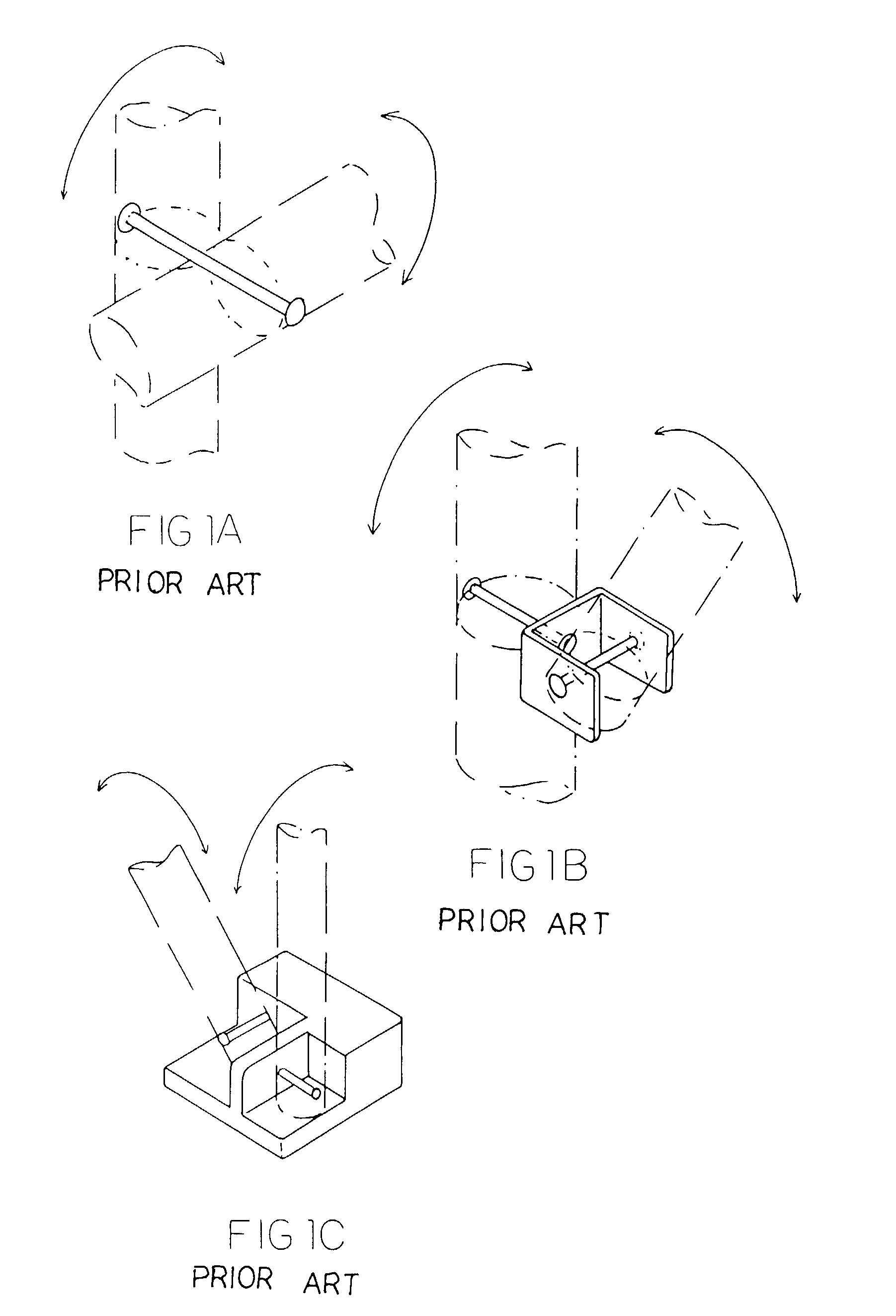
a folding joint and furniture technology, applied in the field of folding joint arrangement of foldable furniture, can solve the problems of only being used as a base pivot joint or a top pivot joint, and the pivot joint cannot provide a rigid configuration

Inactive Publication Date: 2006-02-14
IP POWER HLDG
View PDF18 Cites 31 Cited by
  • Summary
  • Abstract
  • Description
  • Claims
  • Application Information

AI Technical Summary

Benefits of technology

[0010]Another object of the present invention is to provide a folding joint arrangement for foldable furniture, which can substantially connect two frame tubes with each other so as to rigidly support a downward force applied on the foldable furniture.
[0011]Another object of the present invention is to provide a folding joint arrangement for foldable furniture, which can substantially reduce a space required to pivotally connect with the frame tubes so that the size of the foldable furniture will not be limited when the foldable furniture is unfolded. In other words, the foldable furniture can be folded into a compact size for storage and carriage.
[0012]Another object of the present invention is to provide a folding joint arrangement for foldable furniture, which does not require altering the original structural design of the foldable furniture, so as to minimize the manufacturing cost of the foldable furniture incorporating with the folding joint arrangement.
[0013]Another object of the present invention is to provide a folding joint arrangement for foldable furniture, wherein no expensive or complicated structure is required to employ in the present invention in order to achieve the above mentioned objects. Therefore, the present invention successfully provides an economic and efficient solution for providing a rigid configuration for the foldable furniture.

Problems solved by technology

However, such pivot joint cannot provide a rigid configuration especially when a downward force is applied on the foldable furniture.
However, such pivot joint can only be used as a base pivot joint or a top pivot joint since the pivot wall is allowed to pivotally connect to the end of each of the first and second construction tubes.

Method used


Image

  • Folding joint arrangement for foldable furniture
  • Folding joint arrangement for foldable furniture
  • Folding joint arrangement for foldable furniture

Examples


Embodiment Construction

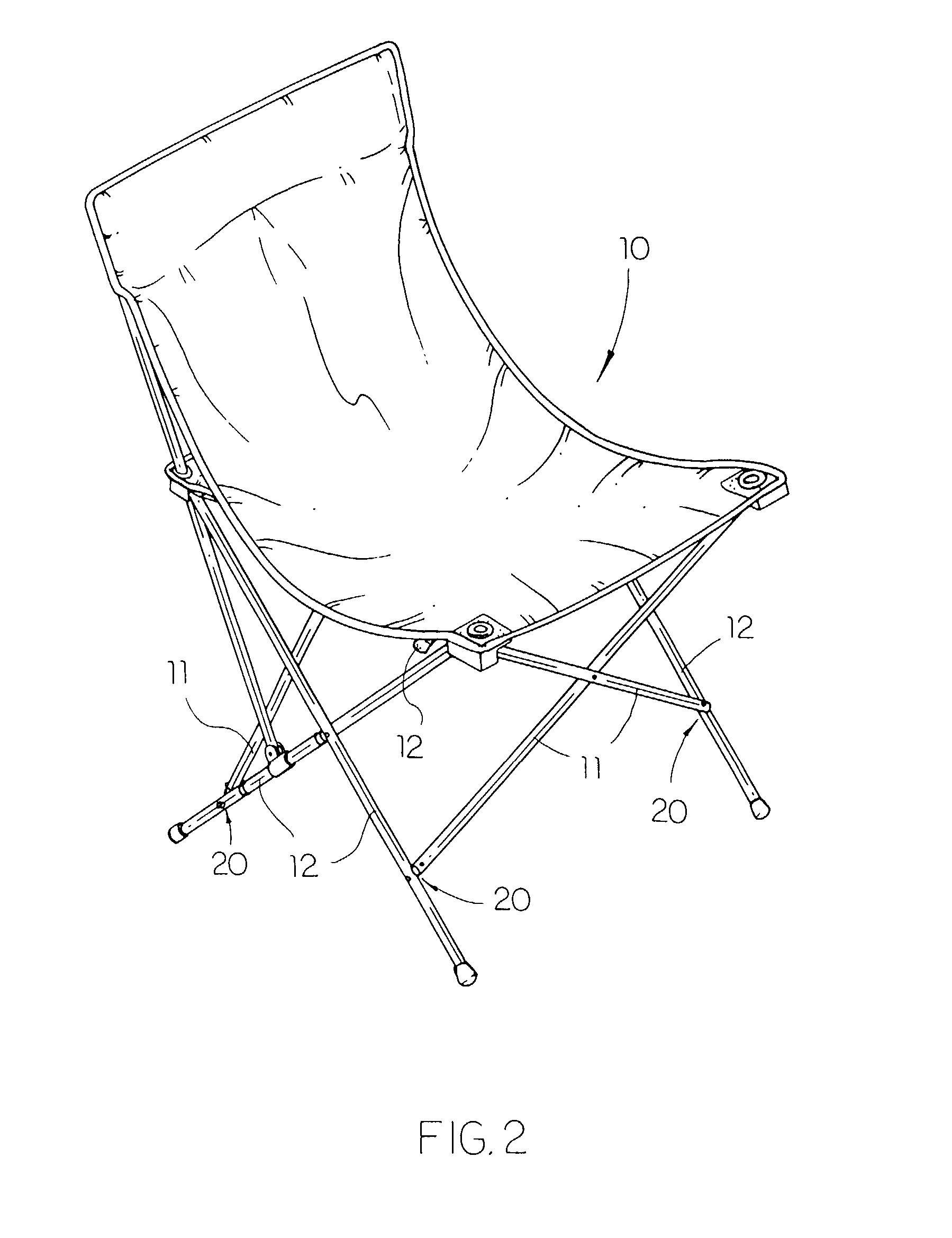
[0026]Referring to FIGS. 2 and 3 of the drawings, a folding joint arrangement 20 incorporated with a foldable furniture 10 according to a preferred embodiment is illustrated, wherein the foldable furniture 10 is embodied as a foldable chair constructed by a plurality of first and second frame tubes 11, 12 pivotally connected with each other via the folding joint arrangement 20.

[0027]As shown in FIG. 2, the foldable chair of the foldable furniture 10 comprises a back frame and a seat frame for supporting a fabric seat. The seat frame comprises a front pair, a back pair, and two side pairs of construction tubes, wherein each of the front and rear pairs of construction tubes is embodied as the first frame tube 11 and each of the side pairs of construction tubes is embodied as the second frame tube 12.

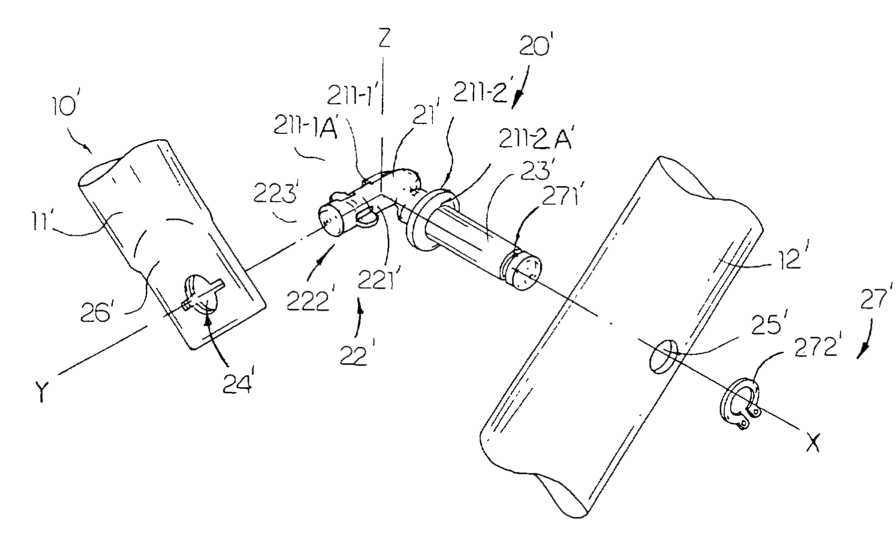
[0028]Referring to FIG. 3, the folding joint arrangement 20 comprises an angle joint body 21, a pivot arm 22 integrally extended from the angle joint body 21 to define a first axis 220, wh...


PUM


Abstract

A folding joint arrangement, which is adapted for incorporating with a foldable furniture constructed by a plurality of first and second frame tubes, includes an angle joint body, a pivot arm integrally extended from the angle joint body to define a first axis, wherein the pivot arm is adapted for pivotally connecting with one of the first frame tube such that the first frame tube is capable of rotating about the first axis of the pivot arm, and a connector arm integrally extended from the angle joint body to define a second axis perpendicularly to the first axis wherein the connector arm is adapted for pivotally connecting with one of the second frame tube such that the second frame tube is capable of rotating about the second axis of the connector arm, so as to pivotally connect the first and second frame tubes in a two-plane directional movement.

Description

BACKGROUND OF THE PRESENT INVENTION[0001]1. Field of Invention[0002]The present invention relates to a foldable furniture, and more particularly to a folding joint arrangement for the foldable furniture, which is capable of rigidly two frame tubes in a pivotally movable manner so as to provide a two-plane directional movement of the foldable furniture.[0003]2. Description of Related Arts[0004]A conventional foldable furniture is constructed by a plurality of metal tubes pivotally connected with other in such a manner that the foldable furniture is capable of folding into a compact size and unfolding to expanse its supporting size by means of the pivot movement of the metal tubes.[0005]For example, a foldable c hair comprises a foldable c hair frame comprising a plurality of construction tubes to construct a back frame and a seat frame for supporting a fabric seat. The seat frame comprises a front pair, a back pair, and two side pairs of construction tubes, wherein each pair of the c...

Claims


Application Information

Patent Timeline
Patent Type & Authority Patents(United States)
IPC IPC(8): A47C4/00A47C4/28A47C4/38A47C5/04E05D3/10F16B7/08
CPCA47C5/04E05D3/10E05Y2900/20Y10T403/32008Y10T403/7194Y10T403/3906Y10T403/32606Y10T403/7123Y10T403/71Y10T403/32951A47C4/286A47C5/10
Inventor ZHENG, EDWARD
Owner IP POWER HLDG
Why Eureka
Try Eureka