Welding gun

a welding gun and insulating material technology, applied in the field of welding guns, can solve the problems of difficult, if not impossible, difficult, removal of insulating materials, etc., and achieve the effect of increasing the size or weight of the welding gun and increasing the amp

Inactive Publication Date: 2006-02-14
KENSRUE MILO M
View PDF21 Cites 28 Cited by
  • Summary
  • Abstract
  • Description
  • Claims
  • Application Information

AI Technical Summary

Benefits of technology

[0010]It would also be advantageous to provide a welding gun with cooled torch barrel and a larger welding tip so that larger amps can be used without appreciably increasing the size or weight of the welding gun.

Problems solved by technology

This technique for insulating the torch barrel has become unsatisfactory because during manufacturing the compression molding may collapse the tubes in the torch barrel, in which case the torch barrel is discarded.
In addition, if the torch barrel becomes damaged after being sold, the insulating material is difficult to remove, making repairs to the torch barrel difficult if not impossible.
Another problem associated with the Cobra™ welding gun is that the gas and water tubes extend through the handle, around the wire feeding mechanism and into the torch barrel.
In addition, if the torch barrel is damaged the entire length of the gas and cooling fluid tubes must be replaced.

Method used


Image

  • Welding gun
  • Welding gun
  • Welding gun

Examples


Embodiment Construction

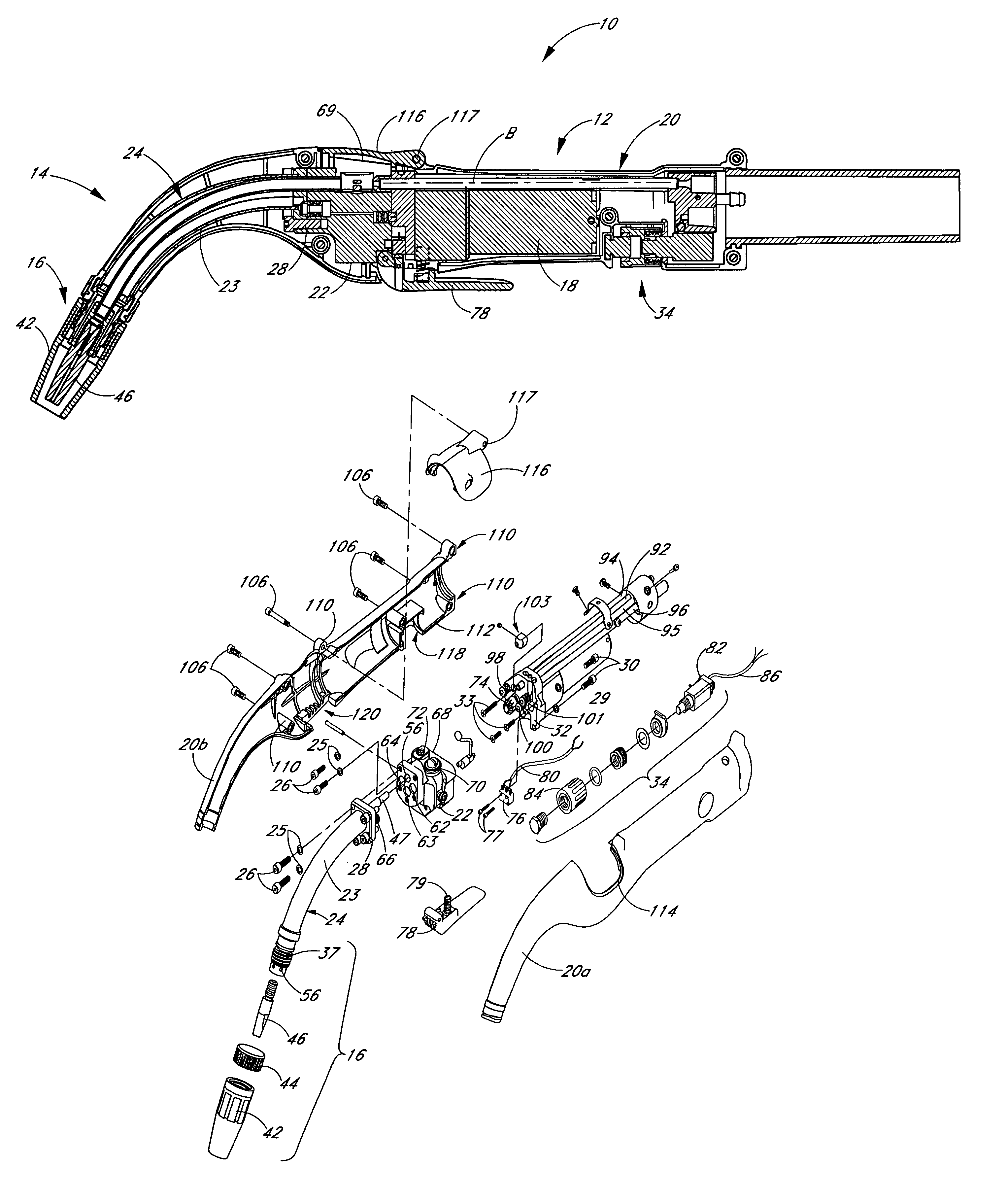
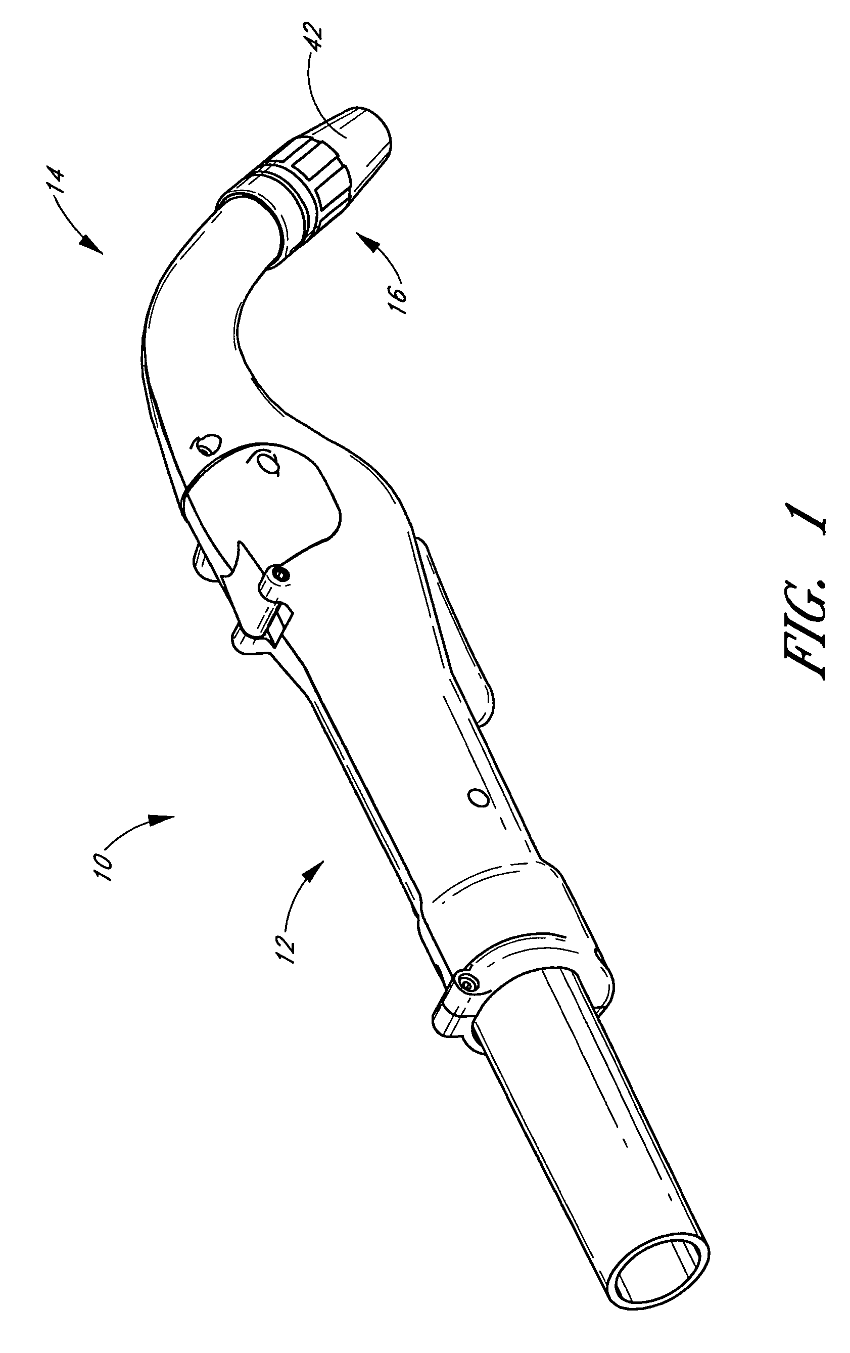
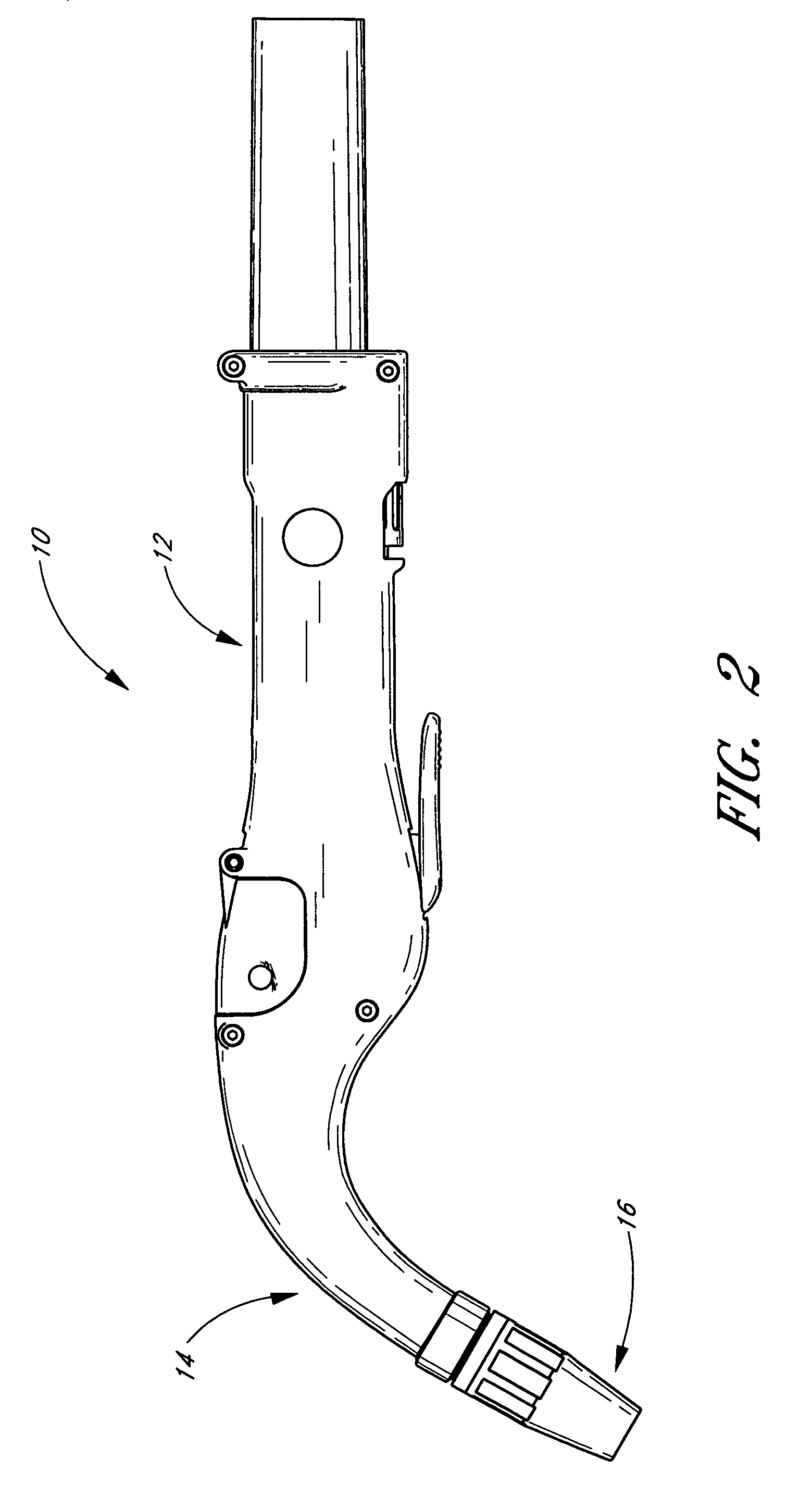
[0023]FIGS. 1 and 2 are a perspective and a side view of an illustrated embodiment of a welding gun 10 having certain features and advantages according to the present invention. In the illustrated embodiment, the gun 10 includes a handle 12, a torch barrel section 14 and a welding tip 16. FIG. 3 is a cross-sectional view of the gun 10 and illustrates a motor 18, which is positioned inside the handle 12 generally along the longitudinal axis of the gun 10. The illustrated gun 10, therefore, is an “in-line” welding gun. The handle 12 and barrel section 14 are covered by a substantially rigid, two-piece molded plastic casing 20a, 20b, which is best seen in FIG. 4 and will be described in more detail below.

[0024]With particular reference to FIGS. 3 and 4, the gun 10 includes a block 22, which is preferably made of aluminum. A torch barrel assembly 24 (see also FIG. 5) is removably attached to a distal end of the block 22 by washers 25 and bolts 26, which extend through a barrel mount 28 ...


PUM

PropertyMeasurementUnit
widthaaaaaaaaaa
lengthaaaaaaaaaa
sizeaaaaaaaaaa

Abstract

An in-line welding gun includes a mounting block, a wire feed mechanism and a torch barrel. A motor is positioned behind the mounting block along a longitudinal axis of the gun. The torch barrel curves away from the longitudinal axis. The motor and the torch barrel are surrounded by a substantially rigid shell comprising a tubular portion and a torch portion.

Description

PRIORITY INFORMATION[0001]This application claims the priority benefit under 35 U.S.C. § 119(e) of Provisional Application 60 / 435,615 filed Dec. 19, 2002.BACKGROUND OF THE INVENTION[0002]1. Field of the Invention[0003]This invention relates to a welding gun and, in particular, to an in-line MIG welding gun.[0004]2. Description of the Related Art[0005]A MIG welding gun generally comprises a handle, a wire feed mechanism, a motor for driving the wire feed mechanism and a torch barrel. The welding gun typically also includes a gas tube and a cooling fluid tube for supplying gas and cooling fluid to the tip of the torch barrel.[0006]There are two general types of welding guns: pistol grip and in-line welding guns. In a pistol grip gun, the motor is located below the wire feed mechanism and lies along an axis that lies generally perpendicular to the longitudinal axis of the gun. In contrast, in an in-line gun, the motor lies along the longitudinal axis of the gun and is positioned genera...

Claims


Application Information

Patent Timeline
Patent Type & Authority Patents(United States)
IPC IPC(8): B23K9/00
CPCB23K9/133B23K9/295B23K9/285
Inventor KENSRUE, MILO M.
Owner KENSRUE MILO M
Why Eureka
Try Eureka