Method and apparatus for displaying 3d images

a 3d image and apparatus technology, applied in static indicating devices, instruments, optical elements, etc., can solve the problems of not being able to use devices in practice, requiring more space, etc., to increase the number of emitting directions, reduce costs, and improve resolution

Inactive Publication Date: 2006-02-14
BALOGH
View PDF18 Cites 84 Cited by
  • Summary
  • Abstract
  • Description
  • Claims
  • Application Information

AI Technical Summary

Benefits of technology

[0018]Preferably, the image generating means is a micro-display. The integrated circuit technology has made the production of the above devices in smaller size—practically in the size of an IC—usually with a pixel size of 10–15 microns with higher resolution and at lower costs. This makes recommended large number parallel operating micro-display based systems / apparatus feasible.
[0020]It has also proven practical for the apparatus to contain several devices producing essentially parallel light beams, which have a common light source, preferably any intensive light source, mirror light bulbs or metal-halide lamps. This way the light of the common light source is directed to the individual optical deflection devices through optical fibres. This significantly simplifies the structure of the lighting system, the distribution of the light to the large number of modules, and the light source can be placed further from the lenses and its cooling can be better implemented.
[0022]It is also viable in some applications that the screen provides a retroreflective surface. This arrangement is advantageous, when the observer of the three-dimensional image moves in a relatively narrow space and the different views are to be created within that space only.
[0024]The invention eliminates the theoretical disadvantage of known systems operating on a three-dimensional parallel display theory in that it uses significantly smaller image point generating means than the final 3D (complex) image. The image point generating means are used in an appropriate geometry. This can help avoid the sub-pixel structure that lead to bad filling (the so-called stadium display or fence effect, resolution reduction, etc.). Light passes light beams without obstacle and is emitted from the same (screen) point instead, when using the image generating method in accordance with the invention.

Problems solved by technology

The basic problem is how to generate the required number of imaging screen points (spots) within a given unit of time (spot / sec):
Such a device is not yet available in practice, or is only able to display a limited number of views.
The disadvantage of this approach is that it requires more space.

Method used


Image

  • Method and apparatus for displaying 3d images
  • Method and apparatus for displaying 3d images
  • Method and apparatus for displaying 3d images

Examples


Embodiment Construction

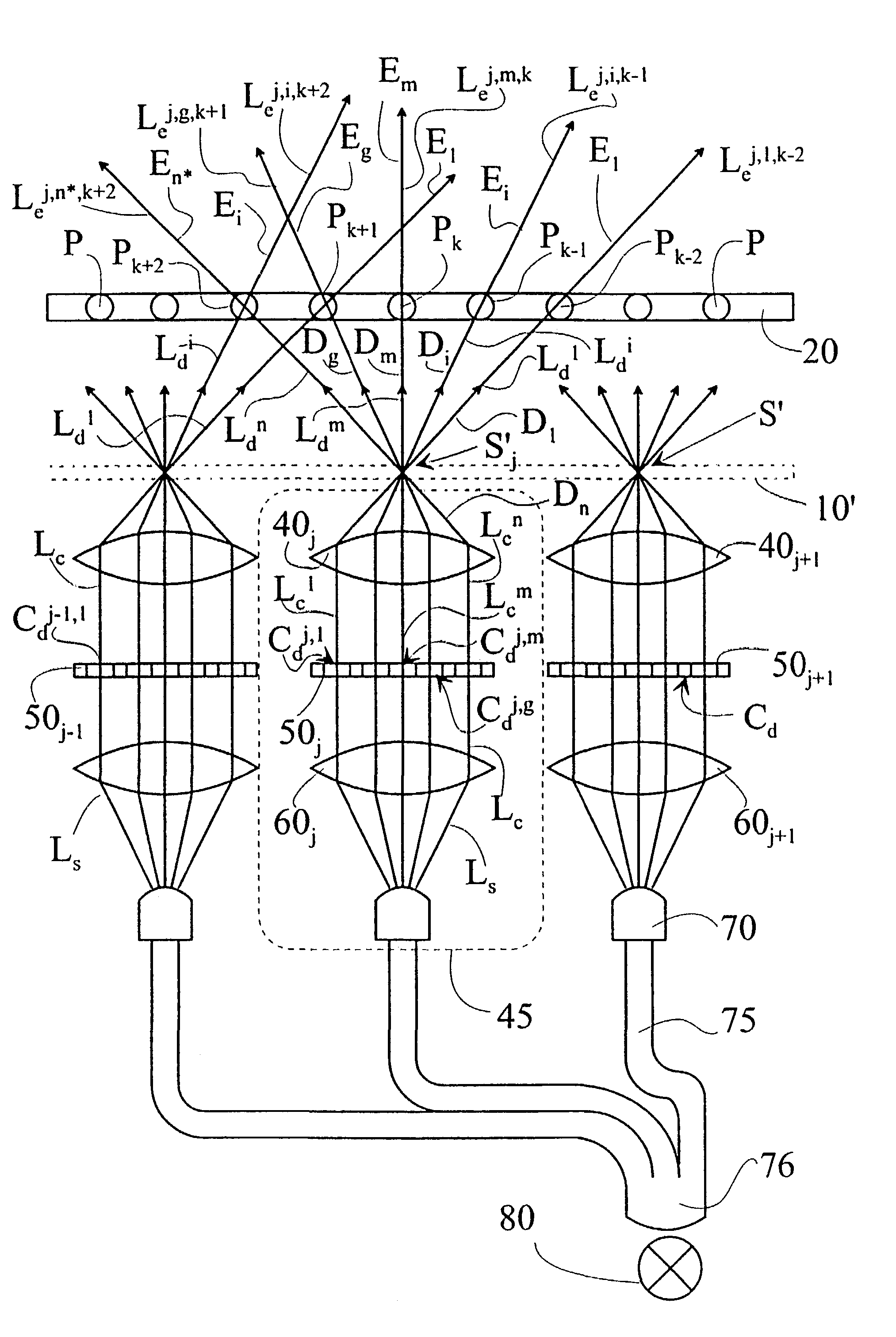
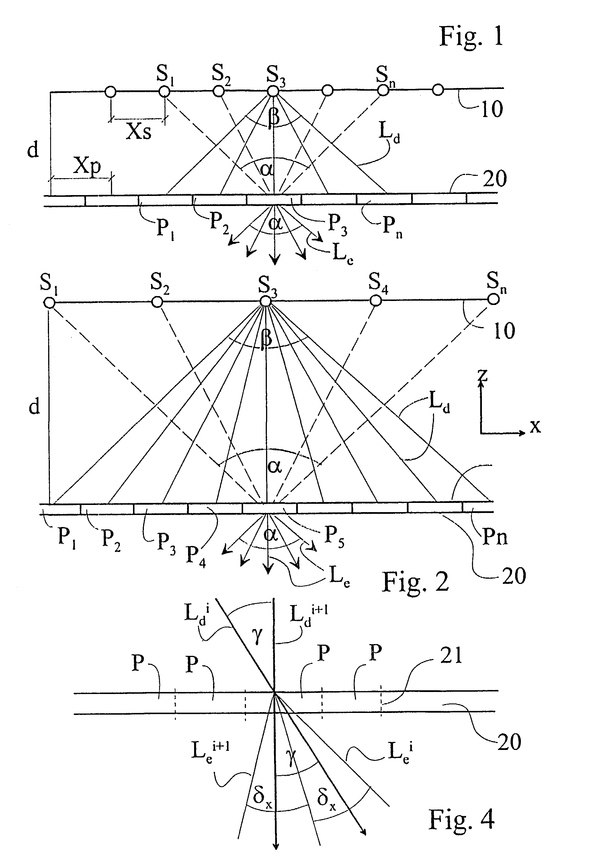
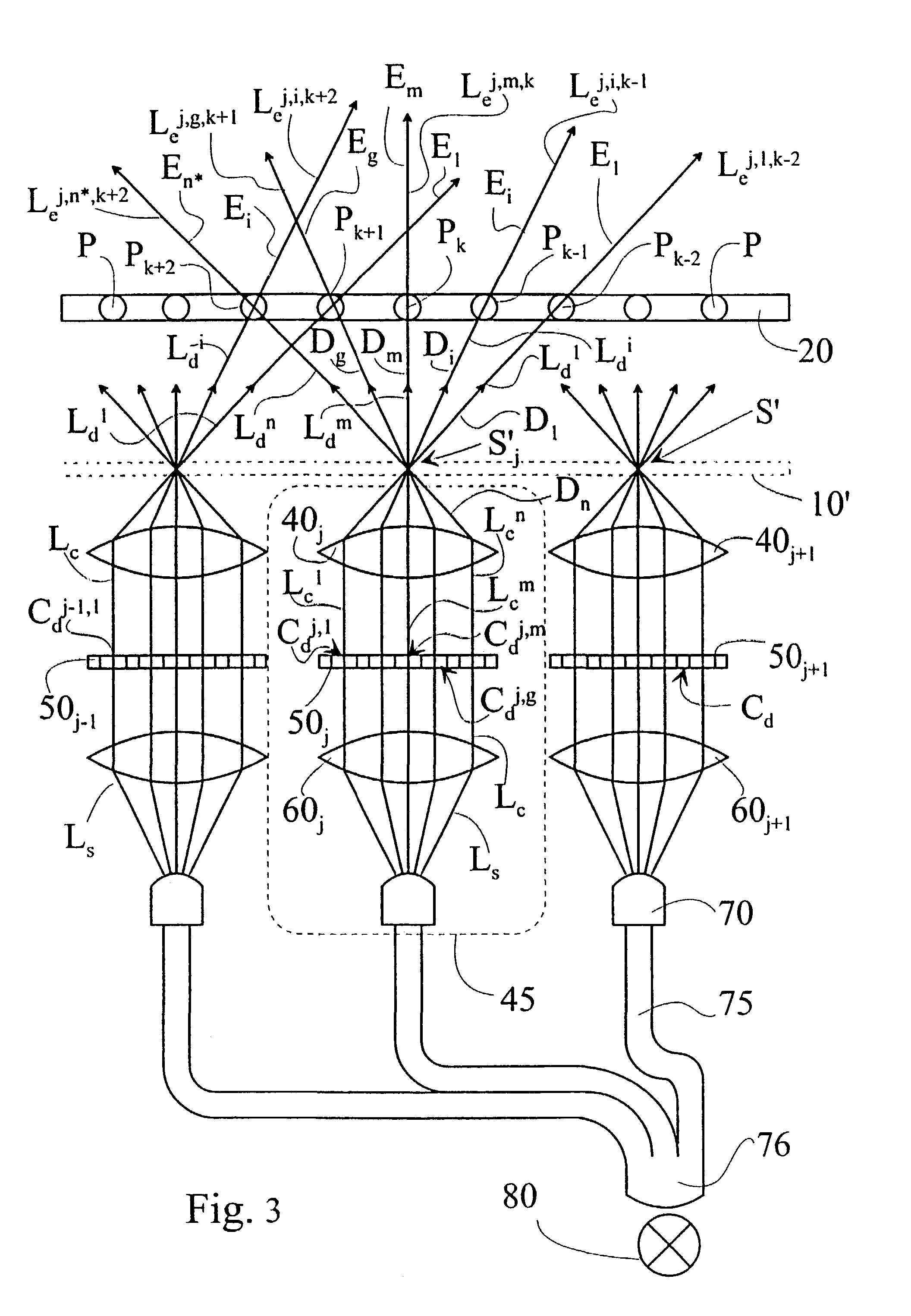
[0076]With reference to FIGS. 1–3 we explain the principle of the invention through presenting the apparatus. The apparatus is to provide three-dimensional images with a sense of space. This is fulfilled by the screen of the apparatus emitting different light beams in different emitting directions as explained in detail in FIG. 6. For that purpose the apparatus has a screen 20 that transmits and / or reflects light direction selectively. By the direction selectivity of the screen we mean that the exiting light beam Lc exits the screen 20 depending of the incident angle of the deflected light beam Ld arriving at the screen 20, i.e. a well defined emitting angle is associated to a given incident angle. In other words, the direction of the incident light beam Ld explicitly determines the direction of the exiting light beam Le, as opposed to diffuse screens, where after the incidence of a light beam other light beams exit in a relatively wide space angle and the direction of the incident ...


PUM


Abstract

The invention relates to a method for displaying three-dimensional images. In the method light beams (Le) are associated to several different screen points (P) of a screen (20). The light beams (Le) produce different views associated to different emission directions (E). The emission directions (E) are associated to the individual screen points (P). The light beams (Le) are generated by projecting light beams (Ld), according to the angle of the adjacent emitting directions. According to the invention, light beams (Le) without viewing direction information are generated, essentially simultaneously, with pixels (Cd) having different co-ordinates. These pixels (Cd) are pixels of a two-dimension display (50), and they are associated to different emitting directions (E) of the appropriate screen points (P). The light beams (Le) produced by the pixels (Cd) of the display (50) with different co-ordinates are imaged simultaneously in different deflection directions (D), as a function of the co-ordinates of the pixels (Cd) producing the light beams (Le). The subject of the invention is an apparatus implementing the above method.

Description

TECHNICAL FIELD[0001]The invention relates to a method for displaying 3D images, in the course of which light beams associated to multiple different points of a screen and light beams creating different views associated to different emitting directions of the individual screen points are generated, and the light beams thus generated are projected onto a directionally selective transmitting and / or reflecting screen. The subject of the invention also relates to the apparatus implementing the method of the invention. The apparatus comprises a screen for direction selectively transmitting and / or reflecting light, and a screen illuminating system. The screen illuminating system comprises modules for generating light beams; the light beams being associated to multiple different points of the screen, and to different emitting directions of the points of the screen. The modules are controlled by an appropriate control system.BACKGROUND ART[0002]Three dimensional (3D) imaging methods based o...

Claims


Application Information

Patent Timeline
Patent Type & Authority Patents(United States)
IPC IPC(8): G09G3/36G02B30/27H04N13/00
CPCG02B27/2214G02B30/27
Inventor BALOGH
Owner BALOGH
Why Eureka
Try Eureka