Electronic component mounting apparatus and electronic component mounting method
a technology for mounting apparatuses and electronic components, applied in the direction of manufacturing tools, instruments, packaged goods types, etc., can solve the problems of increasing the size of the total of the apparatus, difficulty in promoting an operational efficiency, and difficulty in manual handling of background art, etc., to achieve excellent operational efficiency
- Summary
- Abstract
- Description
- Claims
- Application Information
AI Technical Summary
Benefits of technology
Problems solved by technology
Method used
Image
Examples
embodiment 1
(Embodiment 1)
[0020]An embodiment of the invention will be explained with reference to the drawing as follows.
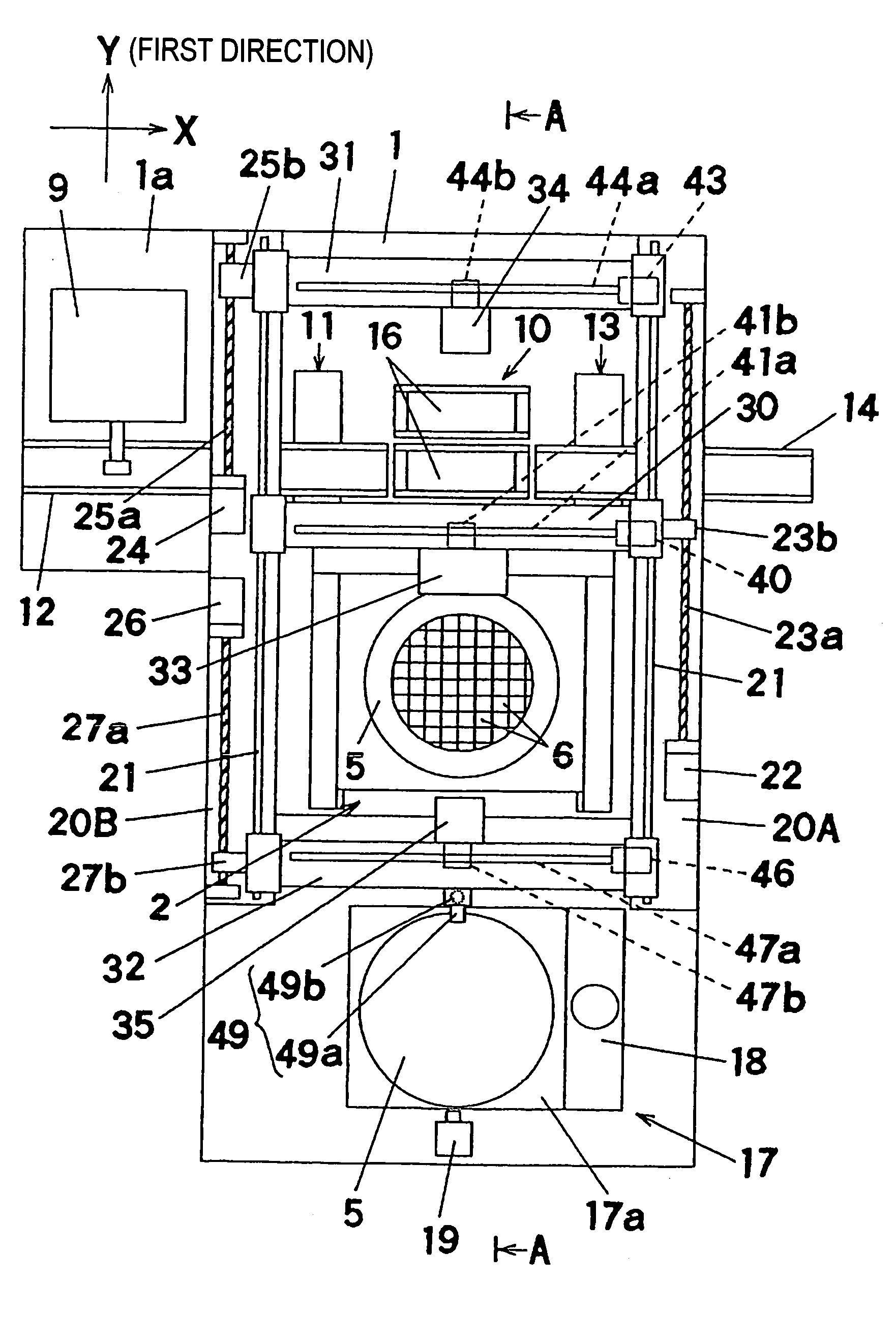
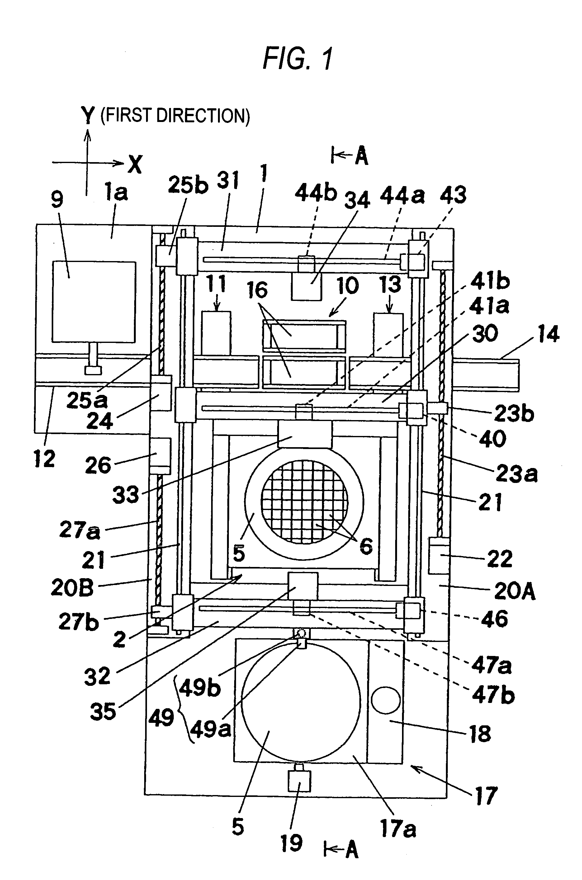
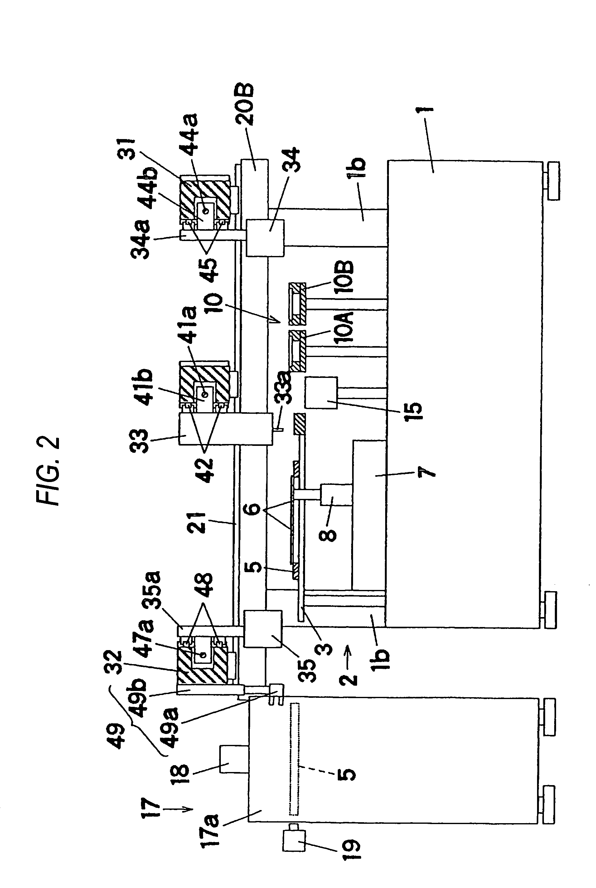
[0021]An explanation will be given of a total structure of an electronic component mounting apparatus with reference to FIG. 1 and FIG. 2. FIG. 2 shows a section taken along a line A—A of FIG. 1. In FIG. 1, an electronic component supply portion 2 is arranged on a base 1. As shown by FIG. 2, the electronic component supply portion 2 is provided with a wafer holding table 3, and the wafer holding table 3 detachably holds a wafer ring 5 which is a component holding jig. A sheet (illustration thereof is omitted) expanded to the wafer ring 5 is pasted with semiconductor chips 6 (hereinafter, abbreviated simply as “chip 6”) which are electronic components in a state of being separated to individual pieces thereof and in a state of holding the wafer ring 5 at the wafer holding table 3, the electronic component supply portion 2 supplies the chips 6 held by being aligned by a plural...
embodiment 2
(Embodiment 2)
[0063]Next, another embodiment of the invention will be explained in reference to the drawing.
[0064]First, an explanation will be given of a total structure of an electronic component mounting apparatus in reference to FIG. 7 and FIG. 8. FIG. 8 shows a section taken along line A—A of FIG. 7. In FIG. 7, a board carrying path 102 is arranged above a base 101 in X direction. The board carrying path 102 carries a board 103 mounted with an electronic component to an electronic component mounting position to position to hold. Therefore, the board carrying path 102 constitutes a board holding portion arranged at a position remote from an electronic component supply portion 104 in Y direction (first direction).
[0065]As shown by FIG. 8, the electronic component supply portion 104 is provided with a jig holder 107 and the jig holder 107 is detachably mounted with a wafer ring 105 for holding a sheet pasted with a semiconductor chip 106 (hereinafter, abbreviated simply as “chip 1...
PUM
| Property | Measurement | Unit |
|---|---|---|
| size | aaaaa | aaaaa |
| size | aaaaa | aaaaa |
| weight | aaaaa | aaaaa |
Abstract
Description
Claims
Application Information
 - R&D
- Intellectual Property
- Life Sciences
- Materials
- Tech Scout
- Unparalleled Data Quality
- Higher Quality Content
- 60% Fewer Hallucinations
Browse by: Latest US Patents, China's latest patents, Technical Efficacy Thesaurus, Application Domain, Technology Topic, Popular Technical Reports.
© 2025 PatSnap. All rights reserved.Legal|Privacy policy|Modern Slavery Act Transparency Statement|Sitemap|About US| Contact US: help@patsnap.com


