Cam assisted wheel brake

a technology cams, which is applied in the field of assisted wheel brakes, can solve the problems of catastrophic failure, loss of all function, and inability to have as much power of scissor brakes, and achieve the effect of increasing the force applied to the arms

Inactive Publication Date: 2006-02-21
CIAMILLO THEODORE J
View PDF11 Cites 33 Cited by
  • Summary
  • Abstract
  • Description
  • Claims
  • Application Information

AI Technical Summary

Benefits of technology

[0005]The present invention is an improvement of the previously existing scissor brake. It utilizes a lever cam to increase the force applied to the arms. It also provides a novel quick release mechanism to open the brake slightly in the event the rim is damaged; this keeps the pads from rubbing on the rim in the open position. Furthermore, the present invention provides a plastic spring for opening the brake, which provides a lighter solution than a steel spring.

Problems solved by technology

However, the scissor brakes usually do not have as much power as the dual pivot style.
These brakes are also cast or forged aluminum which does not bend much before breaking, therefore if the brake does fail, the failure is catastrophic and all function is lost.

Method used


Image

  • Cam assisted wheel brake
  • Cam assisted wheel brake
  • Cam assisted wheel brake

Examples


Embodiment Construction

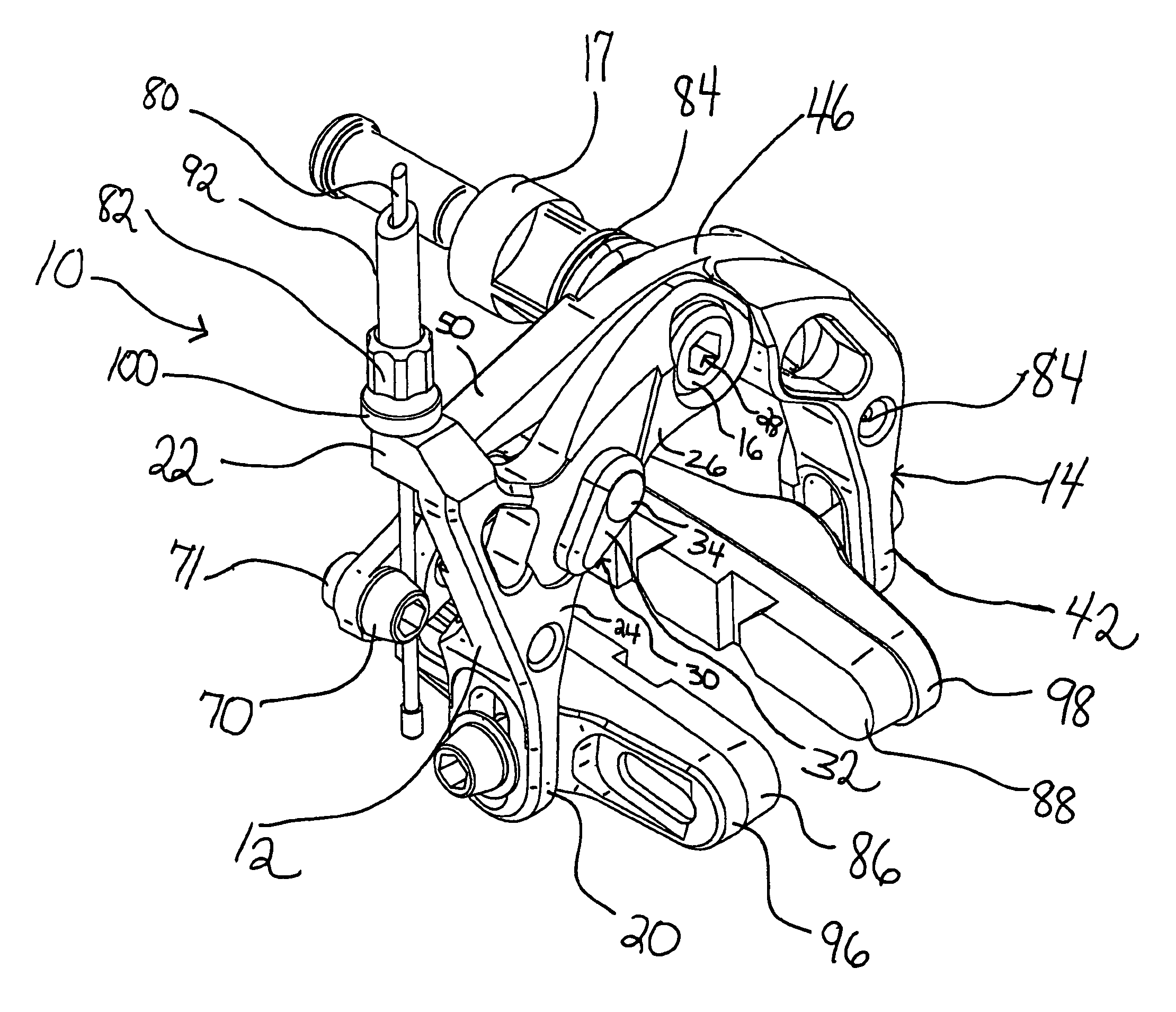
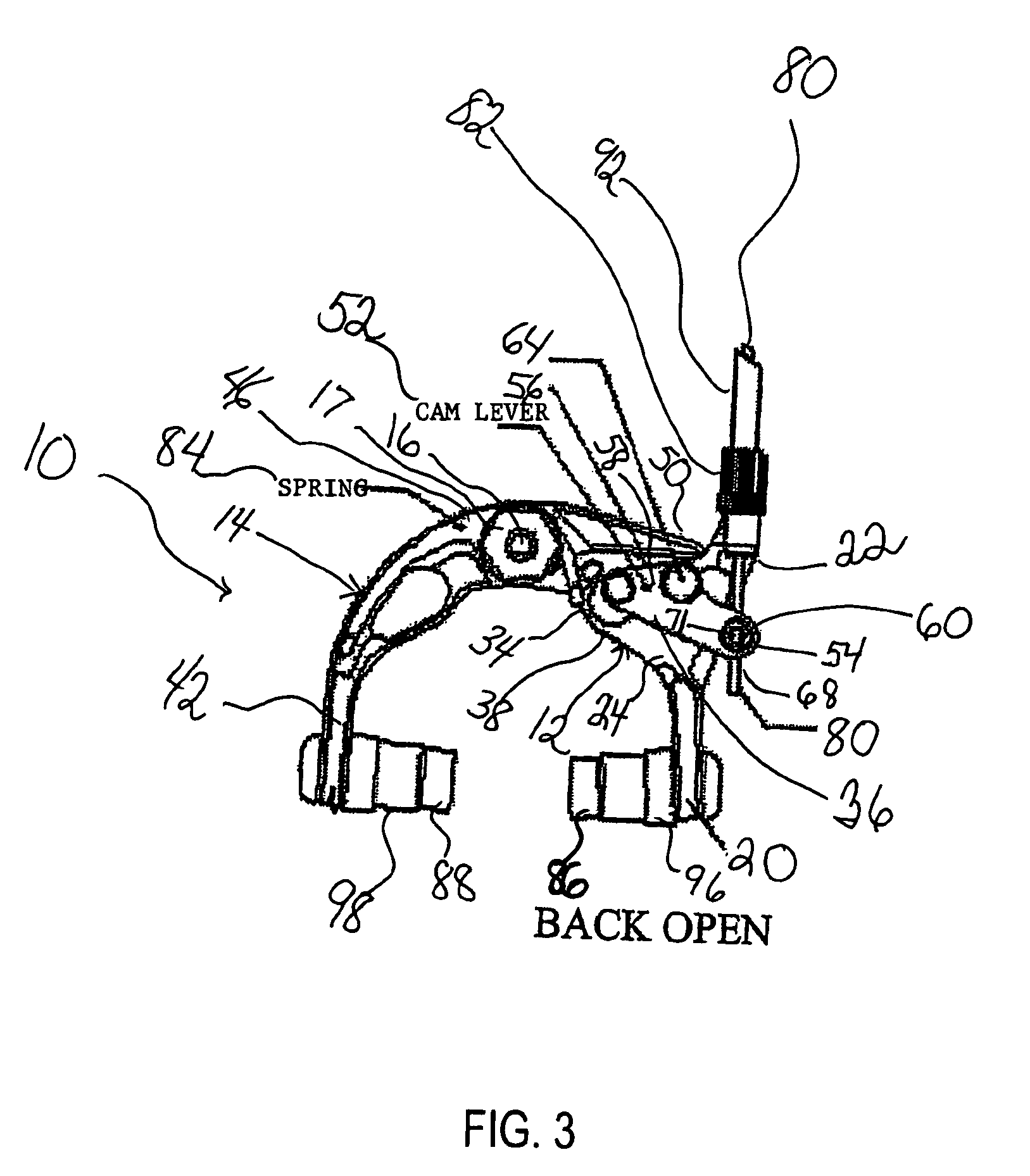
[0017]An exemplary embodiment of the invention is a brake device 10 shown FIGS. 3–8. The brake device 10 comprises a first arm 12 and a second arm 14 mounted on a bolt 16, which provides a pivot point for the arms 12, 14 and a means for attachment of the brake 10 to a fork of a bicycle or other wheeled vehicle. The bolt 16 has a nut 17 which is used to secure the brake device 10 to the vehicle.

[0018]The first arm 12 comprises a downward depending brake pad attachment portion 20, a cable attachment portion 22, a middle portion 24 and a pivot portion 26 attached via a bore 28 (not visible in the FIGS., but is known to those of ordinary skill in the art) to the bolt 16. The middle portion 24 receives a quick release latch 30. The quick release latch 30 comprises a finger operable lever 32 having a first pin portion 34 which extends through one side of a latch middle portion 36 to the other side of a latch middle portion 36. A secondary pin portion 38, which is offset from the axis of t...


PUM


Abstract

A cam assisted wheel brake for a bicycle comprising two arms mounted on a bolt, which provides a pivot point for the arms and a means for attachment of the brake to the fork of the bicycle. The brake incorporates a cam lever pivotably associated with the first arm and which engages a finger portion of the second arm and which comprising a first portion having a screw passing through a bore, a middle portion having a top edge having a curved edge portion, and a second portion pivotably connected to the first arm by a pin extending therethrough. The invention preferably has a quick release mechanism comprising a lever having a first pin extending therefrom, the pin pivotably engaging a bore in the first arm, and a second pin extending off axis from the first pin and pivotably engaging the second portion of the cam lever.

Description

CROSS-REFERENCE TO RELATED APPLICATION[0001]This application claims the benefit to provisional application No. 60 / 417,027, filed on Oct. 7, 2002, entitled CAM ASSISTED WHEEL BRAKE, the disclosure of which is incorporated by reference in its entirety herein.FIELD OF THE INVENTION[0002]This present invention relates to brakes for road bicycles and other wheeled vehicles.BACKGROUND OF THE INVENTION[0003]There are a number of bicycle brakes of various designs on the market, most of which are either scissor type brakes (FIG. 1) or dual pivot (FIG. 2). There are advantages to both designs. The idea is to build in enough leverage to develop the necessary power to stop the bicycle while at the same time keeping the size and weight of the brake to a minimum. In each of these designs, the brakes draw two opposing pads onto each side of the rim of the bike wheel. The brake squeezes the rim of the wheel between the two pads using a cable, two arms which hold the pads, and a lever at the handle ...

Claims


Application Information

Patent Timeline
Patent Type & Authority Patents(United States)
IPC IPC(8): B62L3/00B60T11/04B62L1/06
CPCB62L1/06B60T11/046
Inventor CIAMILLO, THEODORE J.
Owner CIAMILLO THEODORE J
Why Eureka
Try Eureka