Conveyor system

a conveyor and belt technology, applied in the direction of conveyors, conveyor parts, cleaning, etc., to achieve the effect of reducing power consumption, simple and cost-efficient design, and reducing friction

Inactive Publication Date: 2006-02-21
BRUKS MEKANISKA
View PDF19 Cites 30 Cited by
  • Summary
  • Abstract
  • Description
  • Claims
  • Application Information

AI Technical Summary

Benefits of technology

[0014]By providing said guide means it is possible to move said endless belt inside a tube back to the location of said intake end of the delivery tube in spite of the presence of the conveyor means projecting from the top surface of the endless belt, since the belt will in this way be moved with the bottom surface thereof under and following the “ceiling” of the tube with the conveyor means projecting inwardly. This is possible by the fact that the return tube is designed and dimensioned with respect to the width of said belt so as to support transversal end portions of the belt by return tube portions, and by that prevent the endless belt to be bent downwardly through the influence of the gravity.
[0015]This means that any material remaining on the endless belt after passing said discharge end of the delivery tube and falling down from said return portion of the endless belt will be collected by said return tube and not lost. An additional advantage of the conveyor system according to the invention is that the transport of the endless belt inside said return tube will reduce the noise level further with respect to conveyor systems already known.
[0016]Furthermore, another advantage of using a tube for returning the endless belt with respect to the use of a flat plate as in the conveyor system of said US patent application publication is that the endless belt will be self-centering, so that it will be possible to guide the endless belt back along a path including curves.
[0020]According to another embodiment of the invention said return tube is arranged below said delivery tube, which makes it possible to have a simple and cost-efficient design of said guide means.
[0021]According to another embodiment of the invention the conveyor system further comprises means adapted to blow air into the return tube at locations to be covered by the bottom surface of said endless belt for reducing the friction between the internal walls of the return tube and at least one portion of said endless belt while travelling through the return tube. This reduces the consumption of power for feeding the endless belt through the return tube. The same is obtained by arranging means adapted to blow air into the delivery tube at locations to be covered by the bottom surface of said endless belt for reducing the friction from the internal walls of the delivery tube on the bottom surface of the endless belt when travelling through the delivery tube. It is pointed out that the same air blowing means may be used for both the return tube and the delivery tube, but a higher pressure of the air blown into the delivery tube would mostly be appropriate, since the endless belt is in the delivery tube influenced by the gravitation and also by material resting thereon towards internal bottom walls of the delivery tube, while the gravitation will even assist said air to reduce the friction between internal walls of the return tube and most portions of the endless belt in the return tube.

Problems solved by technology

Furthermore, such material not removed from the endless belt will as a consequence of the gravitation and possible vibrations of the belt fall down from said return portion when the belt is moved towards said intake end, which under certain circumstances may result in a not neglectable loss of material.

Method used


Image

  • Conveyor system
  • Conveyor system
  • Conveyor system

Examples


Embodiment Construction

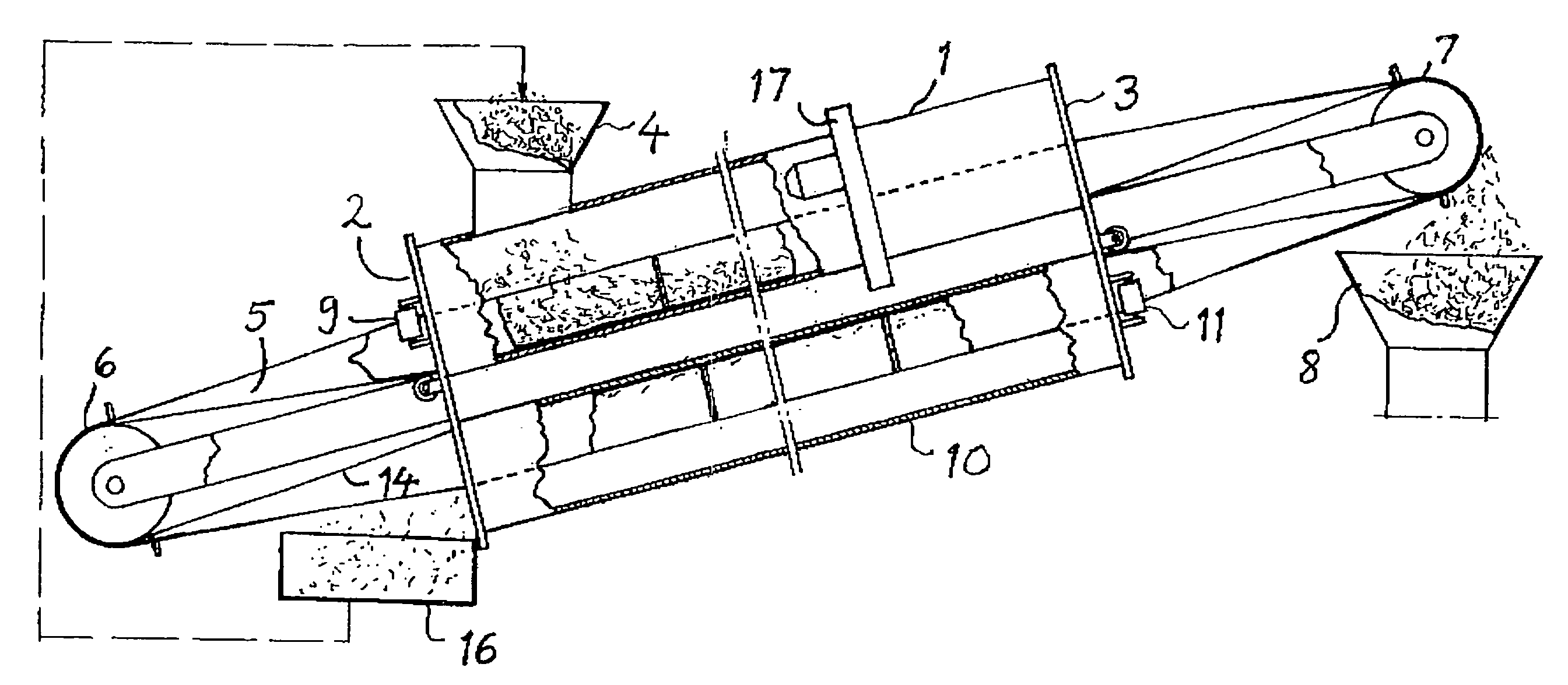
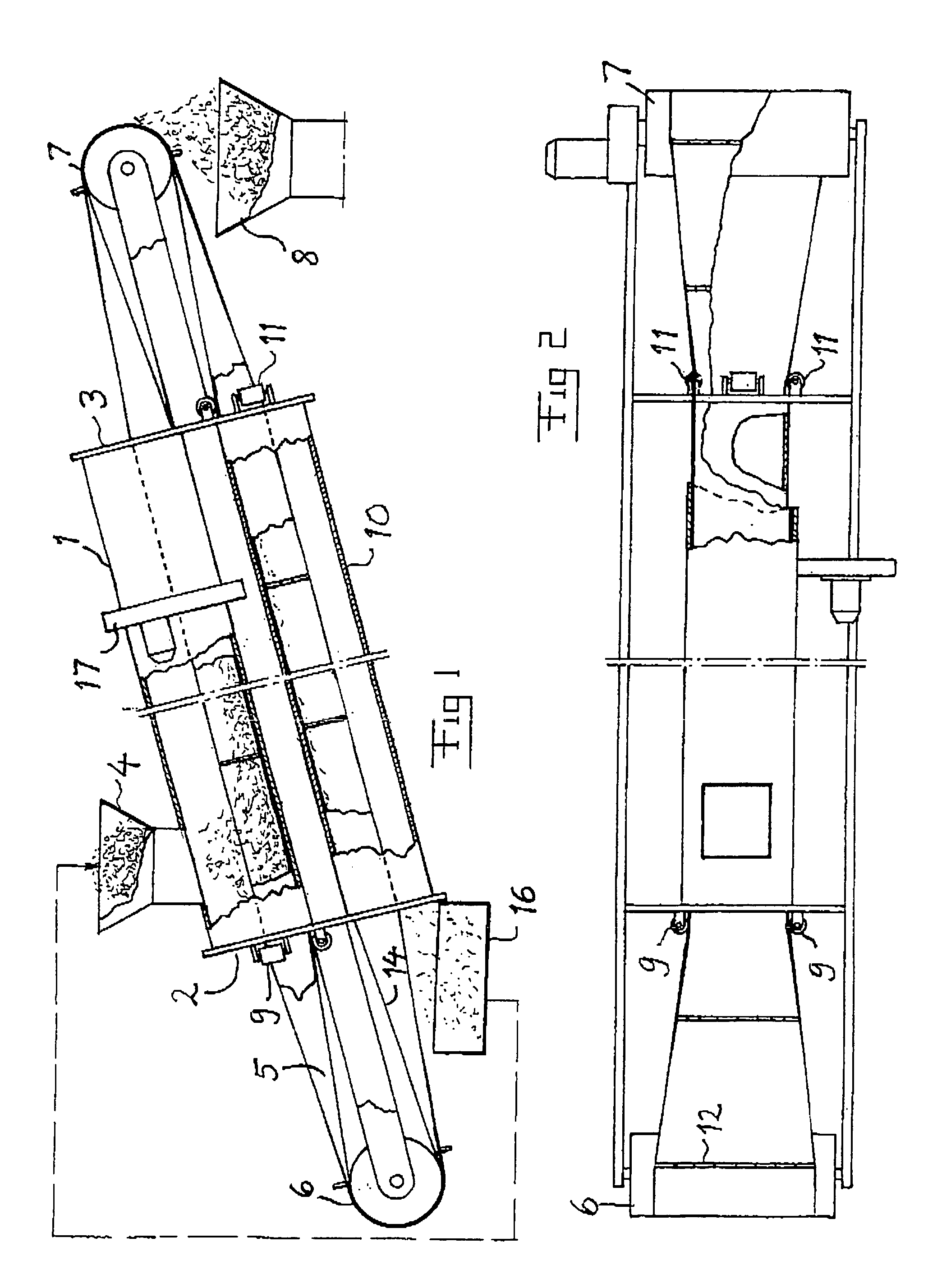
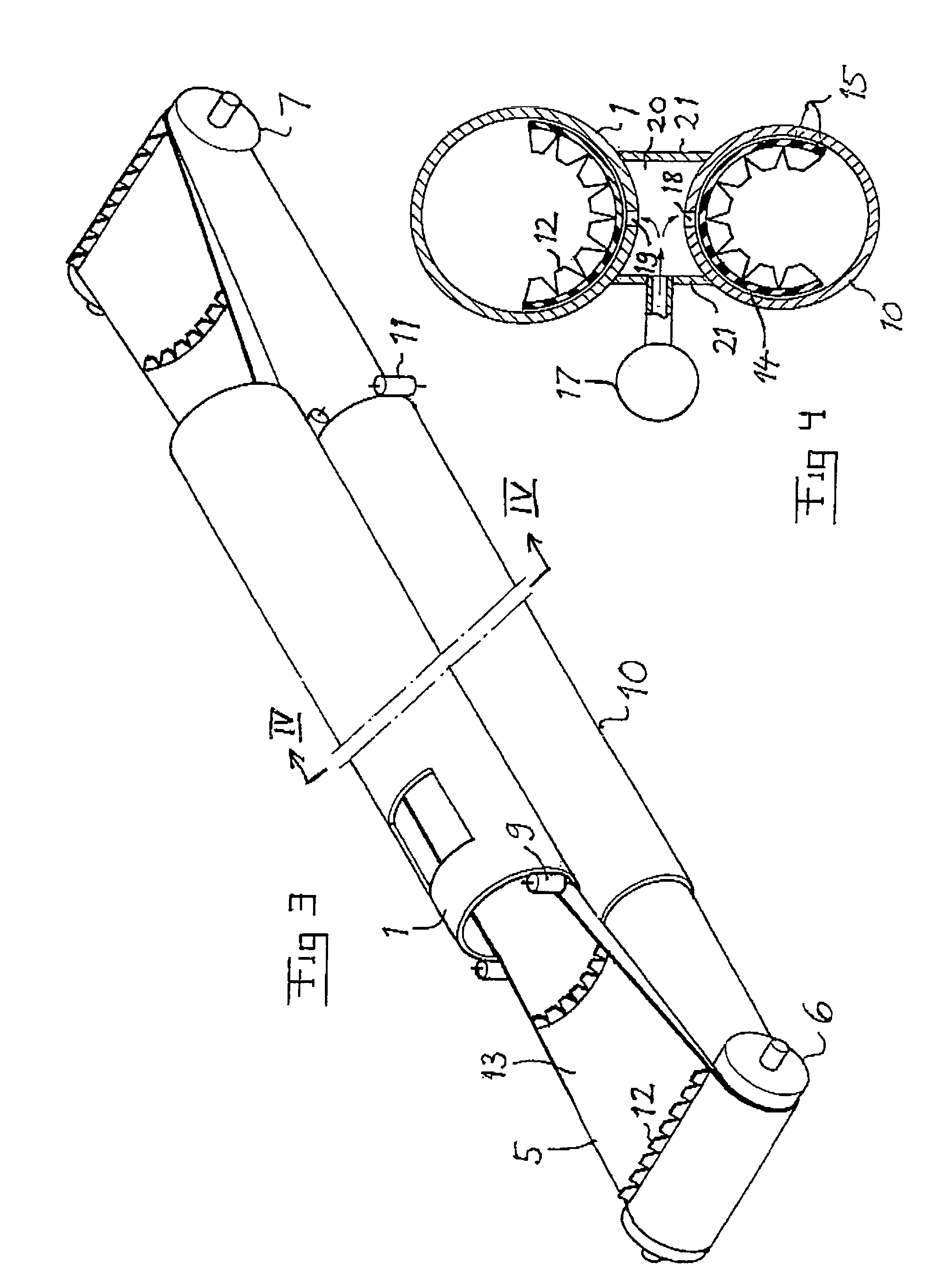
[0032]A conveyor system according to the present invention for transporting bulk material is very schematically illustrated in FIG. 1. The system comprises a delivery tube 1 having an intake end 2 and a discharge end 3. The length of this tube may be 20–300 meters, but the invention is not restricted to this range, and only the two ends thereof are for that sake shown in the Figure. A typical diameter of the tube is 300–1000 millimeters. A member, such as a funnel 4 is arranged at the intake end of the delivery tube supplying bulk material to be fed towards said discharge end to an endless conveyor belt 5.

[0033]The conveyor system also comprises a drive assembly in the form of two pulleys 6, 7 around which the endless conveyor belt 5 is arranged for moving the endless belt by rotating the pulleys.

[0034]A collecting funnel 8 is arranged at the discharge end of the delivery tube 1 for collecting material transported by the endless belt to this location. The location of the discharge e...


PUM


Abstract

A conveyor system comprising an endless conveyor belt (5) having a plurality of mechanical conveyor means (12) projecting from a top surface thereof and a delivery tube (1) having an intake end and a discharge end for receiving a delivery portion of the endless belt and a return tube (10) extending along the delivery tube for receiving a return portion of the endless belt. A drive assembly (6, 7) is mechanically connected to the endless belt for rotating it for moving it in the tubes. Means (9) are arranged to guide the endless belt into the return tube with a bottom surface (14) of the belt following at least the upper portion of the return tube when moving through the return tube. The return tube is designed and dimensioned with respect to the width of said belt so as to support transversal end portions of the belt by return tube portions from below when the belt moves through the return tube while following the upper portion thereof.

Description

BACKGROUND OF THE INVENTION[0001]1. Field of the Invention[0002]The present invention relates to a conveyor system comprising a delivery tube having an intake end, a discharge end, an endless conveyor belt having a top surface and a bottom surface, wherein a delivery portion of said endless belt is positioned within said tube and wherein a return portion of said endless belt is positioned outside said tube, a drive assembly mechanically connected to said endless belt for rotating said endless belt for moving it in said tube from the intake to the discharge end, and a plurality of mechanical conveyor means projecting from said top surface of said endless belt.[0003]Such a conveyor system may be used for transporting different types of materials, especially bulk materials such as chips, cement, gravel and other type of solid material from the location of said intake end to the location of said discharge end of the delivery tube.[0004]The conveyor system may be used within industrial p...

Claims


Application Information

Patent Timeline
Patent Type & Authority Patents(United States)
IPC IPC(8): B65G19/16B65G15/08B65G15/60B65G15/62B65G45/26
CPCB65G15/08B65G15/60B65G45/26B65G15/62B65G2201/04
Inventor BJORKLUND, KARL-GUSTAV
Owner BRUKS MEKANISKA
Why Eureka
Try Eureka