Eureka AIR delivers breakthrough ideas for toughest innovation challenges, trusted by R&D personnel around the world.

Boatlift and movable canopy assembly

a technology of movable canopy and hoist, which is applied in the direction of waterborne vessels, slipways, transportation and packaging, etc., can solve the problems of unfavorable boating safety, inconvenient use, and inability to move the canopy,

Inactive Publication Date: 2006-02-21
EDSON HARVEY WILDER
View PDF8 Cites 21 Cited by
  • Summary
  • Abstract
  • Description
  • Claims
  • Application Information

AI Technical Summary

Benefits of technology

[0006]It is a first non-limiting advantage of the present invention to provide a boatlift assembly having a movable canopy which overcomes the drawbacks associated with prior boat hoists having canopies.
[0007]It is a second non-limiting advantage of the present invention to provide a boatlift assembly which has a movable canopy that automatically moves in the direction opposite to the movement of the boat lifting cradle portion of the boatlift assembly.
[0008]It is a third non-limiting advantage of the present invention to provide a boatlift assembly which has a movable canopy whose movement is confined to moving in the vertical axis.
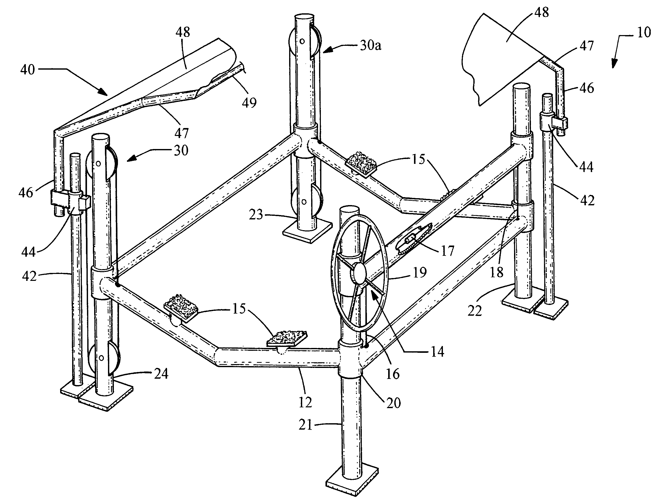
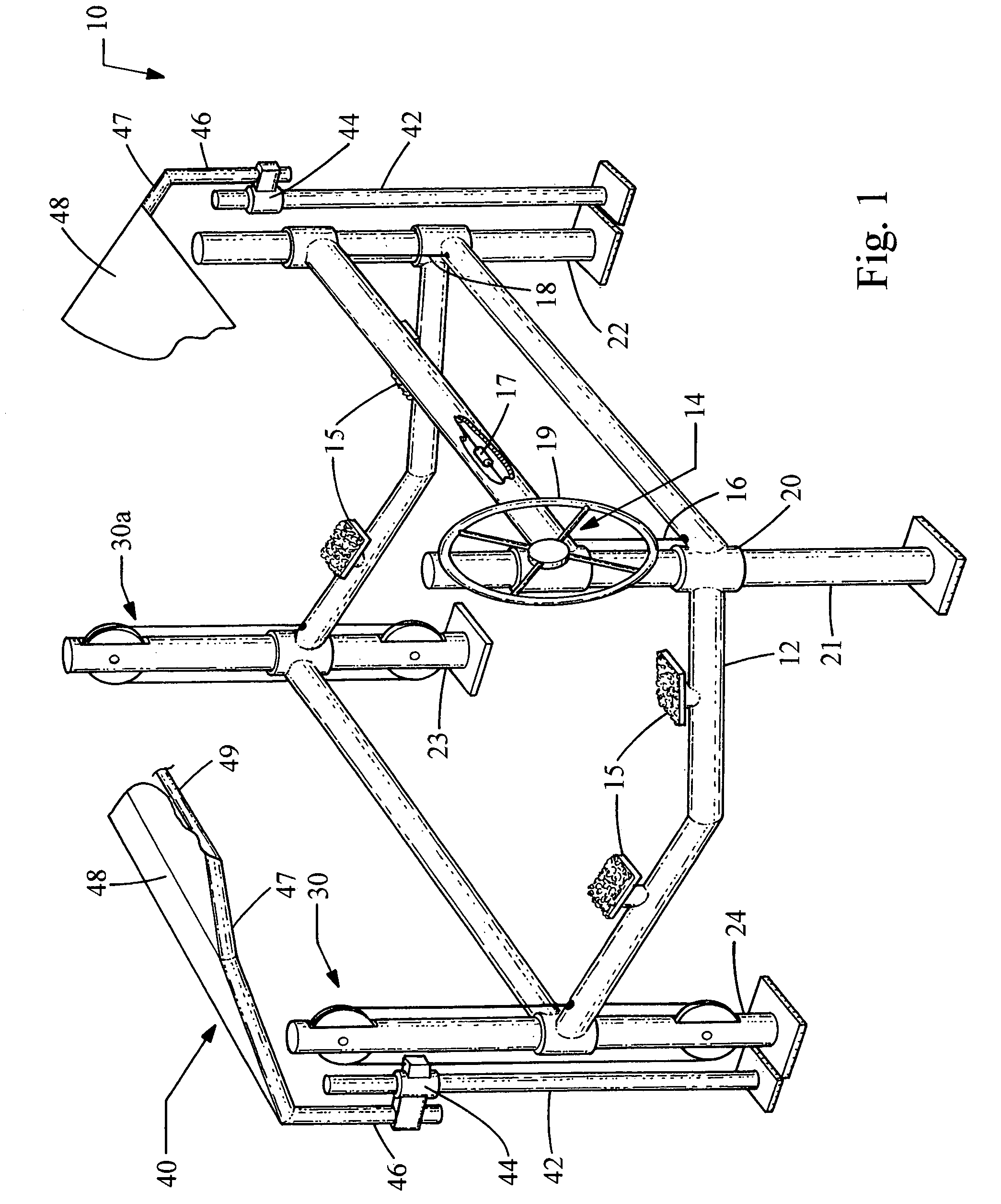
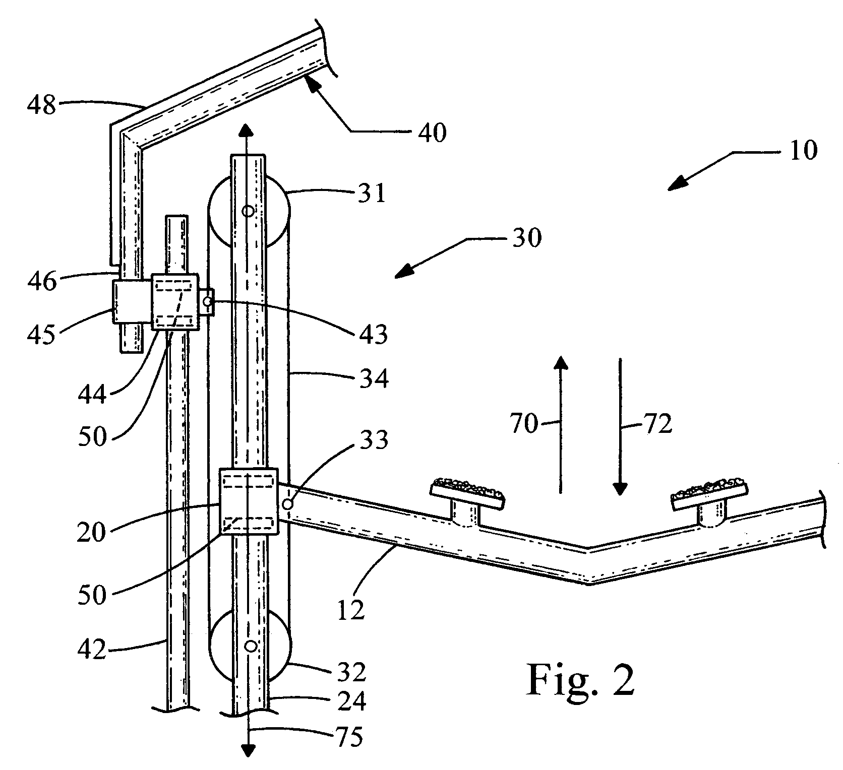
[0009]It is a fourth non-limiting advantage of the present invention to provide a boatlift assembly having four vertical support members; a cradle portion which is slidably coupled to each of the four support members, wherein the cradle portion is effective to abuttingly engage a hull of a boat; a canopy portion which is disposed over the cradle portion; a raising and lowering assembly having a cable and a pair of pulleys, wherein the cradle portion and the canopy portion are coupled to the cable effective to lower the canopy portion when the cradle portion is raised and to raise the canopy portion when the cradle portion is lowered.
[0010]It is a fifth non-limiting advantage of the present invention to provide a boatlift assembly which is effective to lift a boat in a substantially vertical direction, the boatlift assembly including a plurality of vertical support members, wherein the support members are spaced to define an outer periphery of the boatlift assembly; a boat cradle portion which is slidably coupled to each of the plurality of support members, wherein the boat cradle portion is confined to movement in a substantially vertical direction by the support members; a movable canopy portion having an opaque and generally waterproof cover which is disposed over the boat cradle portion, the canopy portion having a plurality of engagement members which confine the movable canopy portion to movement in a substantially vertical direction; and at least one cable and pulley system having a cable and a pair of pulleys, wherein the pair of pulleys are rotatably mounted to a unique one of the vertical support members and wherein the cable is looped around the pair of pulleys and is effective to interconnect the movable canopy portion to the boat cradle portion.
[0011]It is a sixth non-limiting advantage of the present invention to provide a boatlift assembly having four vertical support members, wherein the support members each have a square cross-sectional area, the support members being disposed relative to each other wherein two surfaces of each of the support members are each directed toward one of the other support members; a cradle portion which is effective to lift a boat in a substantially vertical direction, wherein the cradle portion includes four V-shaped wedges, each of which slidably engage a unique one of the four support members along two surfaces of the square cross-sectional area; a canopy portion which is disposed above the cradle portion and which includes four V-shaped wedges which each slidably engage a unique one of the four support members along the two surfaces of the support member which are opposite to the two surfaces which are slidably engaged with the cradle portion; and a raising and lowering assembly which couples the canopy portion to the cradle portion, effective to lower the canopy portion when the cradle portion is raised and to raise the canopy portion when the cradle portion is lowered.

Problems solved by technology

While a canopy does provide protection against the elements, it only provides the maximum benefit if it is relatively close to the boat itself.
A problem occurs, however, in that boaters must have easy access to their boats (i.e., to board and / or load their boats).
These canopies, however, due to their use of hanging cables provide the canopy or cover with an undesirable range of motion which extends beyond the vertical plane (i.e., the canopy is free to move laterally).
This creates the potential for the canopy to undesirably contact the boat (e.g., the canopy may be repeatedly blown into the boat by a strong wind) and cause damage to the boat.

Method used


Image

  • Boatlift and movable canopy assembly
  • Boatlift and movable canopy assembly
  • Boatlift and movable canopy assembly

Examples


Embodiment Construction

[0024]The present invention may be understood more readily by reference to the following detailed description of preferred embodiments of the invention.

[0025]Before the present methods and assemblies are disclosed and described, it is to be understood that the terminology used herein is for the purpose of describing particular embodiments only and is not intended to be limiting. It must be noted that, as used in the specification and the appended claims, the singular forms “a”, “an”, and “the” include plural referents unless the context clearly dictates otherwise.

[0026]At the outset, it should be appreciated that, although the following descriptions of preferred and alternate embodiments are directed towards raising a boat from a body of water while concomitantly covering the raised boat, the applications of the present invention are not limited to lifting only a boat. Rather, as should be appreciated after reading the following detailed description, the present invention may be uti...


PUM


Abstract

A boatlift assembly having a boat cradle portion and a canopy portion. The canopy portion and boat cradle portion are movably coupled to cause the canopy portion to be automatically raised when the boat cradle is lowered and to be automatically lowered when the boat cradle is raised.

Description

FIELD OF THE INVENTION[0001]This application is a continuation in part of U.S. patent application Ser. No. 10 / 650,524 which was filed on Aug. 28, 2003 and which matured into U.S. Pat. No. 6,846,129. The present invention generally relates to a boat hoist assembly and more particularly to a boat hoist assembly which has a movable canopy assembly.BACKGROUND OF THE INVENTION[0002]Boat owners, particularly owners of relatively small boats (e.g., less than twenty five feet in length) oftentimes find it desirable to remove their boats from the lake or other body of water when the boat is not in use (i.e., boats of substantially any desired size or length may also benefit from being removed from the lake or other body of water). In order to lift their boats from the water, various elevating hoist devices have been developed which have a boat cradle portion which lifts the boat vertically to raise the hull of the boat above the waterline. These hoists or lifts permit a boat owner to raise t...

Claims


Application Information

Patent Timeline
Patent Type & Authority Patents(United States)
IPC IPC(8): B63C3/06
CPCB63C3/06
Inventor EDSON, HARVEY WILDER
Owner EDSON HARVEY WILDER
Why Eureka
Eureka Blog
Learn More