Terminal structure and mounting part

a technology of terminals and mounting parts, applied in the direction of cell components, battery connections, cell components, etc., can solve the problems of deteriorating position accuracy, lack of contact stability of both terminals, and inability to design with respect to the loading of components to be loaded so as to achieve the effect of increasing the degree of freedom of design with respect to the loading of components on the main body side apparatus

Inactive Publication Date: 2006-02-21
SONY CORP
View PDF21 Cites 15 Cited by
  • Summary
  • Abstract
  • Description
  • Claims
  • Application Information

AI Technical Summary

Benefits of technology

[0017]Then, an object of the present invention is to lessen the amount of movement necessary for loading a component-to-be-loaded on a main body side apparatus and to aim at miniaturizing the main body side apparatus and the component-to-be-loaded and improving contact stability of the structures of the terminals to achieve electric contact between the main body side apparatus and the component-to-be-loaded.
[0018]The present invention relates to the structures of terminals, and aims for an electric connection between a main body side apparatus and a component-to-be-loaded at the time of the latter being loaded on the former, the main body side apparatus having a main body side terminal and the component-to-be-loaded having a component-to-be-loaded side terminal for joining with the above-mentioned main body side terminal, wherein a terminal piece of the above-mentioned main body side terminal is insert-molded on a mold member with at least one guide piece being integrally provided on the mold member, and a terminal member of the above-mentioned component-to-be-loaded side being insert-molded on a mold member, and a guide groove is formed on the mold member to correspond to the above-mentioned guide piece. By engaging the above-mentioned guide piece with the guide groove formed on the component-to-be-loaded, positioning of the main side terminal and the component-to-be-loaded terminal is achieved.
[0019]In addition, the present invention relates to a component-to-be-loaded having a component-to-be-loaded side terminal for aiming for an electric connection with a main body side terminal of a main body side apparatus when the component-to-be-loaded is loaded on the main body side apparatus, wherein a terminal member of the above-mentioned component-to-be-loaded side terminal is insert-molded with a guide groove being formed on a mold member to correspond to a guide piece provided on the above-mentioned main body side apparatus. By engaging the guide groove with the guide piece of the above-mentioned main body side apparatus, positioning of the above-mentioned main side terminal and the component-to-be-loaded terminal is achieved.
[0020]In such present invention, since positioning of a main body side terminal and a component-to-be-loaded side terminal is achieved by engaging a terminal piece and / or terminal member that is insert-molded on a mold member with a guide piece and a guide groove formed on the mold member, by enhancing the accuracy of molding between the terminal piece and the guide groove of both the terminals, the positional accuracy of the terminal piece and the terminal member of both the terminals can be improved, so that when both the terminals are joined with each other the joining state between the terminal piece and the terminal member can be stably maintained.
[0023]In such present invention, since the flat plate-like contact portions are sandwiched by two contact pieces of the component-to-be-loaded side terminal, and the direction in which the component-to-be-loaded side terminal is inserted into and pulled out from the main body side apparatus is made at least two directions, the direction in which the component-to-be-loaded is loaded on the main body side apparatus can be made different from the direction in which the terminals are joined with each other. As the result, regardless of the direction in which the terminals are joined with each other, the degree of freedom of designing with respect to the loading of the component-to-be-loaded on the main body side apparatus can be increased, and miniaturization of the main body side apparatus and / or component-to-be-loaded can be achieved.

Problems solved by technology

However, as mentioned above, in the conventional structures of terminals, since the sleeve terminal and pin terminal had been embedded in their respective portions by insert molding, positional accuracy can not necessarily be said to have been high, so that there has been a problem in which both the terminals lack in contact stability as the positioning of these terminals depends on the engagement of these terminals.
Namely, although the positional accuracy of one terminal with respect to a body (battery case, battery loading portion) can be increased to some extent, since there are at least two terminals (of late, three terminals in many cases) in the battery pack, positional accuracy between plural terminals tends to deteriorate.
To that extent, there have been difficult problems to aim at miniaturizing the main body side apparatus and / or the component-to-be loaded.
To this end, the battery loading portion of the main body side apparatus had to be provided with an additional space taking into consideration the amounts of sliding of both the terminals, which hampered the miniaturization of the main body side apparatus.
Further, since the above-mentioned main body side terminal (pin terminal) is exposed in the battery loading portion, the possibility is high that it gets deformed by some kind of collisions.
On such occasions, there is a problem in which contact stability at the time of the both terminals being connected further deteriorates.
Particularly, when the battery pack is loaded on the battery loading portion in such a way that the orientation thereof is wrong or the battery pack is forcedly loaded on the battery loading portion by being tilted slantingly, unreasonable force (external force) is applied to the above-mentioned main body side terminal (pin terminal), with a result that there have been many troubles in which the above-mentioned main body side terminal are deformed.

Method used


Image

  • Terminal structure and mounting part
  • Terminal structure and mounting part
  • Terminal structure and mounting part

Examples


Embodiment Construction

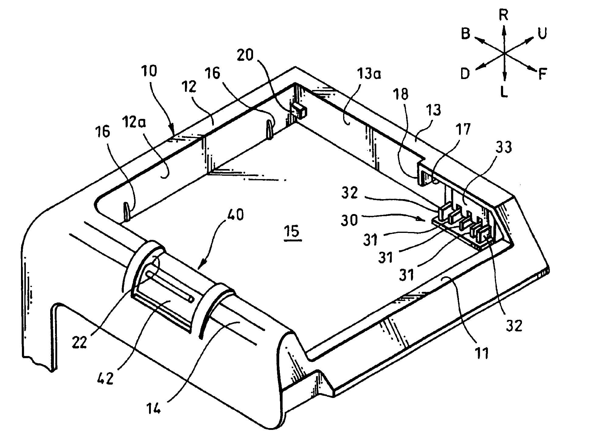
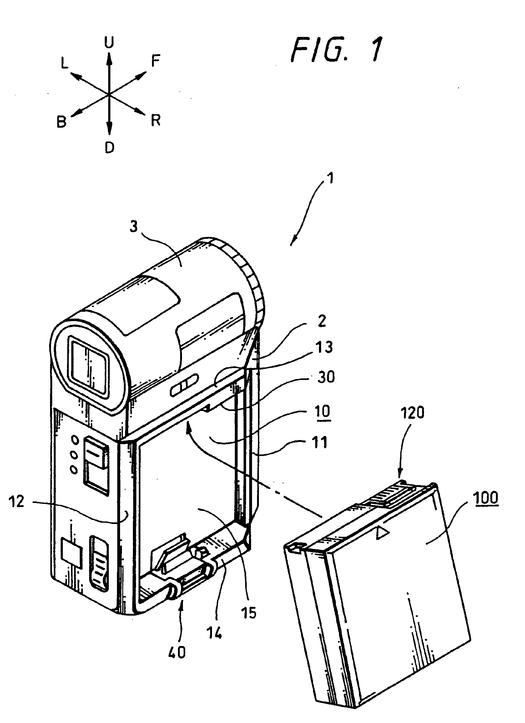
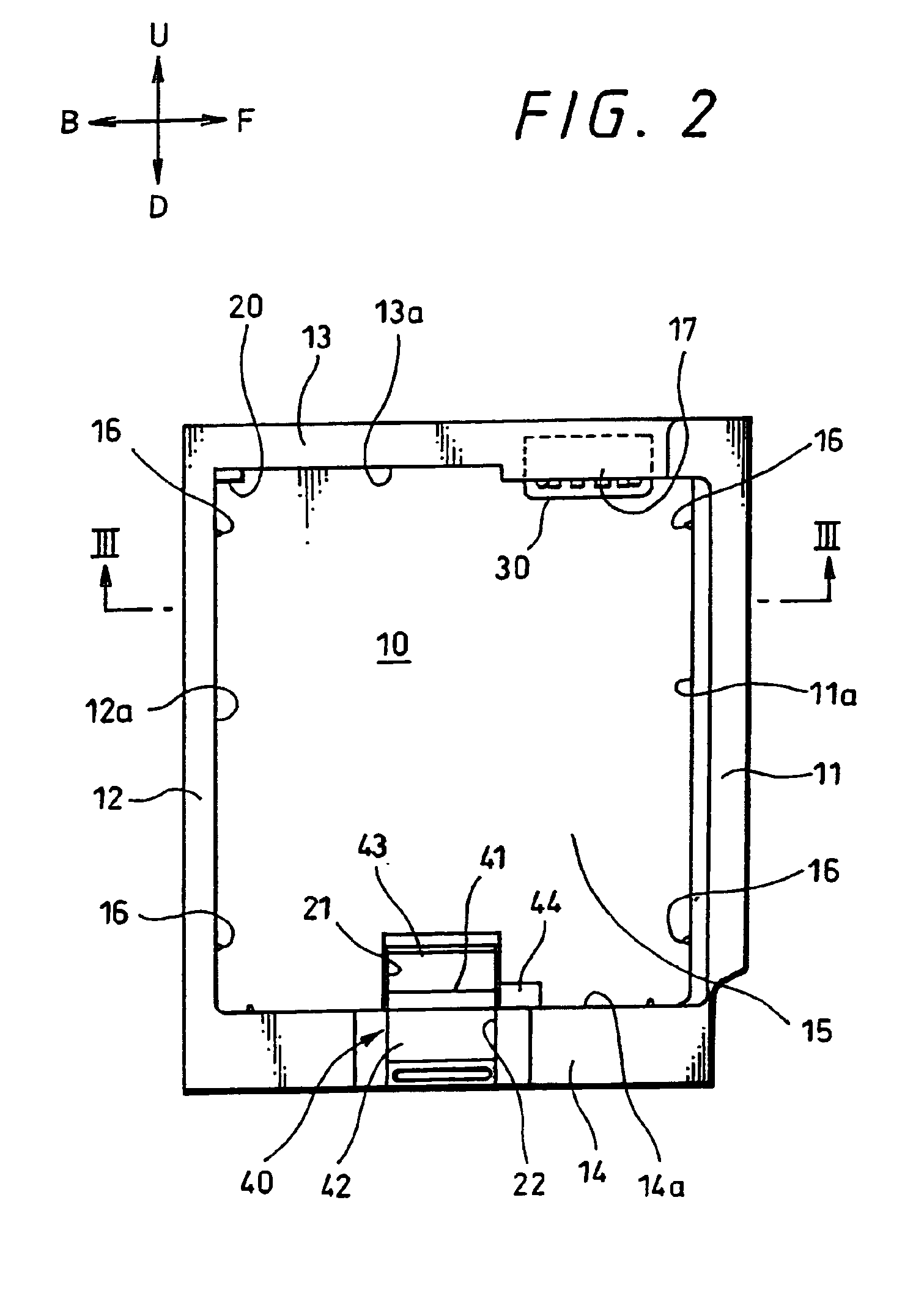
[0064]Hereinafter, the present invention will be explained in detail according to embodiments illustrated in the attached drawings.

[0065]In addition, the embodiments shown in the drawings are such that the present invention is applied to the structure of how the battery pack is loaded in a video camera, wherein ┌video camera┘ corresponds to ┌main body side apparatus┘ described in the scope of claim, and ┌battery pack┘ corresponds to ┌component-to-be-loaded┘ described in the scope of claim, respectively. In addition, ┌video light┘, ┌battery charger┘ to be mentioned later on correspond to ┌main body side apparatus┘, and ┌dry cell pack┘ corresponds to ┌component-to-be-loaded┘ described in the scope of claim, respectively.

[0066]Further, a video camera to be explained in the following is a camera of the type which has a lens body tube positioned at its upper portion of the camera main body when it is in an ordinary state for use with a battery pack removably loaded on the right side surf...


PUM

PropertyMeasurementUnit
thicknessaaaaaaaaaa
thicknessaaaaaaaaaa
engaging forceaaaaaaaaaa

Abstract

Terminal structures aiming for a electric connection when a battery pack 100 (component-to-be-laded) is loaded on a video camera 1 (main body side apparatus), wherein the video camera (main body side apparatus) has a main body side terminal 30, and the battery pack has a battery side terminal 120 (component-to-be-loaded) terminal) for joining with said main body side terminal; and terminal pieces, 31, 31, 31 of said main body side terminal are insert-molded on an upper frame body 13 (mold member with two guide pieces 32, 32, being integrally provided on the upper frame body to sandwich said terminal piece; and a terminal member 122, 122 are insert-molded on a terminal case 121 (mold member)with guide grooves 123, 123 being formed on the terminal case (mold member) to correspond to said guide pieces; and by engaging said guide pieces with the guide grooves formed in the battery pack (component-to-be-loaded), positioning of the main body side terminal and the battery side terminal (component-to-be-loaded side terminal is achieved.

Description

TECHNICAL FIELD[0001]The present invention relates to structures of a main body side apparatus and a component-to-be-loaded that aim for electric contact, and technology to improve the contact stability thereofBACKGROUND ART[0002]As a component-to-be-loaded that aims for electric contact with a main body apparatus, there is provided a battery pack that is loaded on a video camera.[0003]Such a battery pack can be loaded on a video light, a battery charger and the like other than the video camera, and is in need of aiming for electric contact with these appliances all of which are each provided with a terminal of the same form.[0004]Additionally, there are plural-types of batteries based on differences in capacity, and further, as a component-to-be-loaded having a terminal of the same form that is similar to the battery pack, there are, for example, a dry cell pack, a DC plate and the like. By the way, the DC plate is a component-to-be-loaded that has an outer form like the battery pa...

Claims


Application Information

Patent Timeline
Patent Type & Authority Patents(United States)
IPC IPC(8): H01R3/00H01R24/00H01M50/209H01M50/296H01R13/405H02J7/00
CPCH01M2/1066H01M2/30H01R13/64H01R13/405H01R13/629H01R13/03H01R13/112H01R13/62933H01R13/631H01R13/113H01M2220/30Y02E60/10H01M50/103H01M50/209H01M50/296H01M50/20
Inventor EBINE, NOBUHITO
Owner SONY CORP
Why Eureka
Try Eureka