
Dynamic resting hand splint

a wrist and hand technology, applied in the field of dynamic wristhandfinger orthosis or splint, can solve the problems of not being able to extend their wrist or fingers to grasp objects, unable to use cuffs when practical, and no neurological basis of known prior art, etc., to achieve less force and less resistance provided by the tensioner

Active Publication Date: 2006-02-21
SAEBO
View PDF11 Cites 46 Cited by
  • Summary
  • Abstract
  • Description
  • Claims
  • Application Information

AI Technical Summary

Benefits of technology

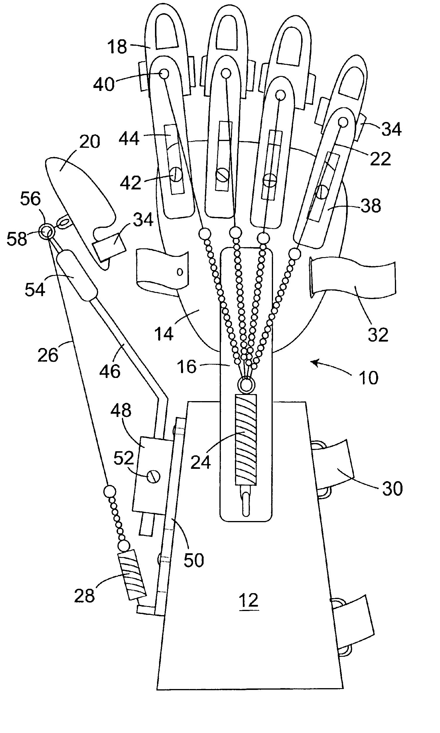
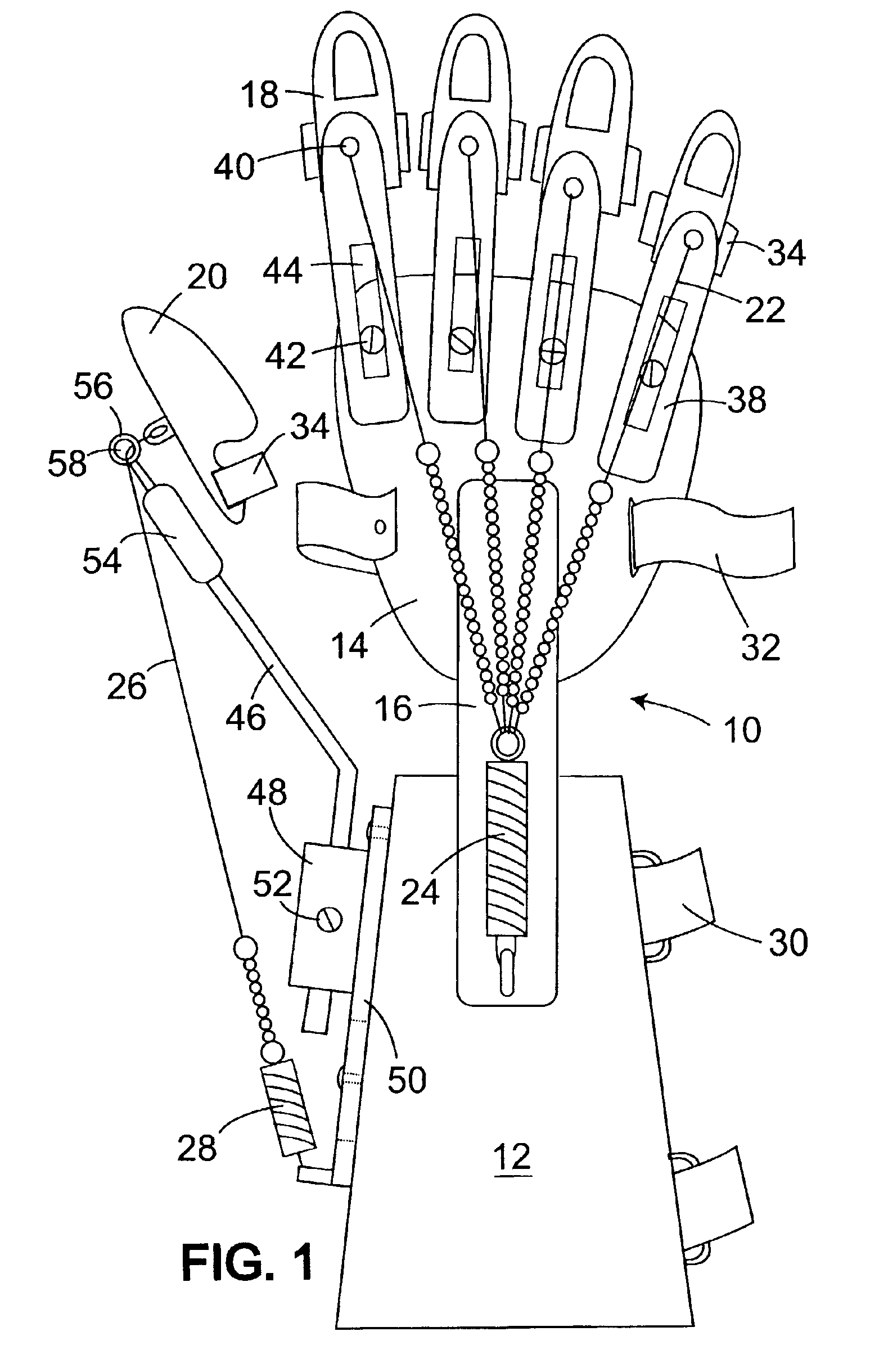
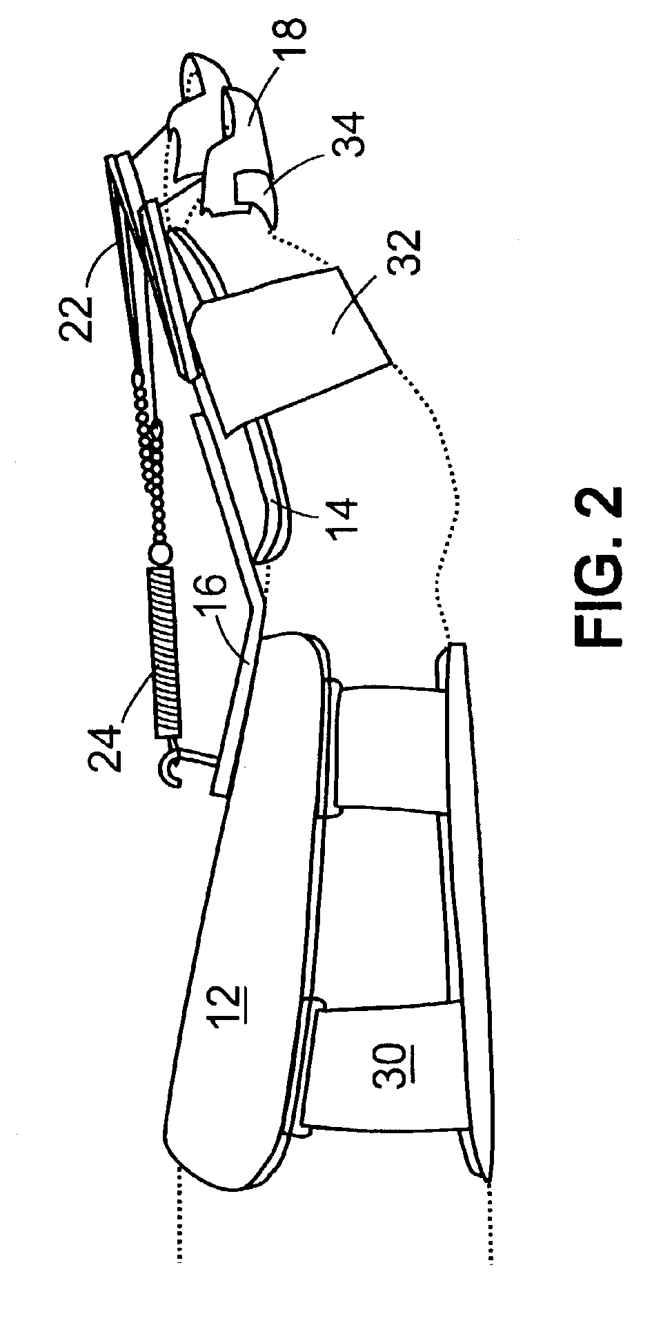
[0021]In operation, the dynamic splint creates rearwardly directed forces that urge the fingers and thumb into an open hand, fingers extended position. Specifically, the finger tensioner constantly pulls on each finger tension line connected to the fingertip caps urging each finger into an extended position...

Problems solved by technology

None of the known prior art is neurologically based and is designed to allow the user to exercise the impaired upper extremity including the wrist, hand, and fingers.
Many have some shoulder and elbow movements, but are unable to extend their wrist or fingers to grasp an object.
These cuffs are not practical when working on a digit affected by hypertonicity, as they move proximal upon closing the fingers, and then have to be repositioned after opening the fingers manually.

Method used


Image

  • Dynamic resting hand splint
  • Dynamic resting hand splint
  • Dynamic resting hand splint

Examples


Embodiment Construction

[0025]In the following description, terms such as horizontal, upright, vertical, above, below, beneath, and the like, are used solely for the purpose of clarity in illustrating the invention, and should not be taken as words of limitation. The drawings are for the purpose of illustrating the invention and are not intended to be to scale.

[0026]As illustrated in the drawings, a preferred embodiment of the dynamic splint, generally 10, of the present invention is comprised of a forearm support 12, a hand support 14, a support connector 16 to connect forearm support 12 and hand support 14 at an upward angle of approximately 25° to 45° degrees, preferably about 35°, raising the user's hand upwardly. A plurality of fingertip caps 18 are positioned over the tips of the user's fingers, while a thumb-tip cap 20 is positioned over the tip of the user's thumb.

[0027]In order to urge fingertip caps 18 from a gripping position to an open position, splint 10 further includes a plurality of adjusta...


PUM


Abstract

A dynamic splint for the positioning and functional exercise of a neurologically impaired upper extremity, including the wrist, hand and fingers, made up of a forearm support and hand support linked by a first connector. Fingertip caps are connected to finger tension leads that extend rearwardly to connect to a finger tensioner attached to the forearm support. The hand support includes adjustable tension lead guides for directing the finger tension leads to the fingertip caps. The dynamic splint also includes a thumb splint assembly made up of a thumb-tip cap connected to a thumb tension lead that extends rearwardly to a thumb tensioner attached to the forearm support. The thumb splint assembly further includes a thumb tension lead guide for directing the thumb tension lead to the thumb-tip cap.

Description

[0001]This application claims the benefit of U.S. Provisional application Ser. No. 60 / 359,810 filed Feb. 25, 2002.BACKGROUND OF THE INVENTION[0002](1) Field of the Invention[0003]The present invention relates to a dynamic wrist-hand-finger orthosis or splint. In particular, the invention is well suited for the positioning and exercise of a neurologically impaired upper extremity, including the wrist, hand, and fingers.[0004](2) Description of the Prior Art[0005]A dynamic wrist-hand-finger orthosis or splint is generally used for the positioning of an impaired, injured, or disabled wrist, hand, and fingers. Splints come in a variety of designs: static, static progressive, and dynamic that can be low profile or high profile.[0006]U.S. Pat. Nos. 5,637,078 and 5,560,375 describe static rigid splints designed to hold the wrist, hand, and fingers in a static position. These splints are used following an injury, during surgery, and post surgery. They are generally made of aluminum with a c...

Claims


Application Information

Patent Timeline
IPC IPC(8): A61F5/00A63B23/16
CPCA63B23/16
Inventor FARRELL, JOHN F.HOFFMAN, HENRY B.
Owner SAEBO
Learn More