Ambient pressure compensated tactile sensor

Inactive Publication Date: 2006-02-28
THE UNITED STATES OF AMERICA AS REPRESENTED BY THE SECRETARY OF THE NAVY
View PDF1 Cites 19 Cited by
  • Summary
  • Abstract
  • Description
  • Claims
  • Application Information

AI Technical Summary

Problems solved by technology

However, the environment in which the sensor may be located may also apply a force to the sensor.
Thus, to overcome a pressure exerted on a tactile sensor by an external environment, a tactile sensor may lack sensitivity desired for a particular application.
When an envi

Method used


Image

  • Ambient pressure compensated tactile sensor
  • Ambient pressure compensated tactile sensor
  • Ambient pressure compensated tactile sensor

Examples


Embodiment Construction

[0018]The following detailed description is of the best currently contemplated modes of carrying out the invention. The description is not to be taken in a limiting sense, but is made merely for the purpose of illustrating the general principles of the invention, since the scope of the invention is best defined by the appended claims.

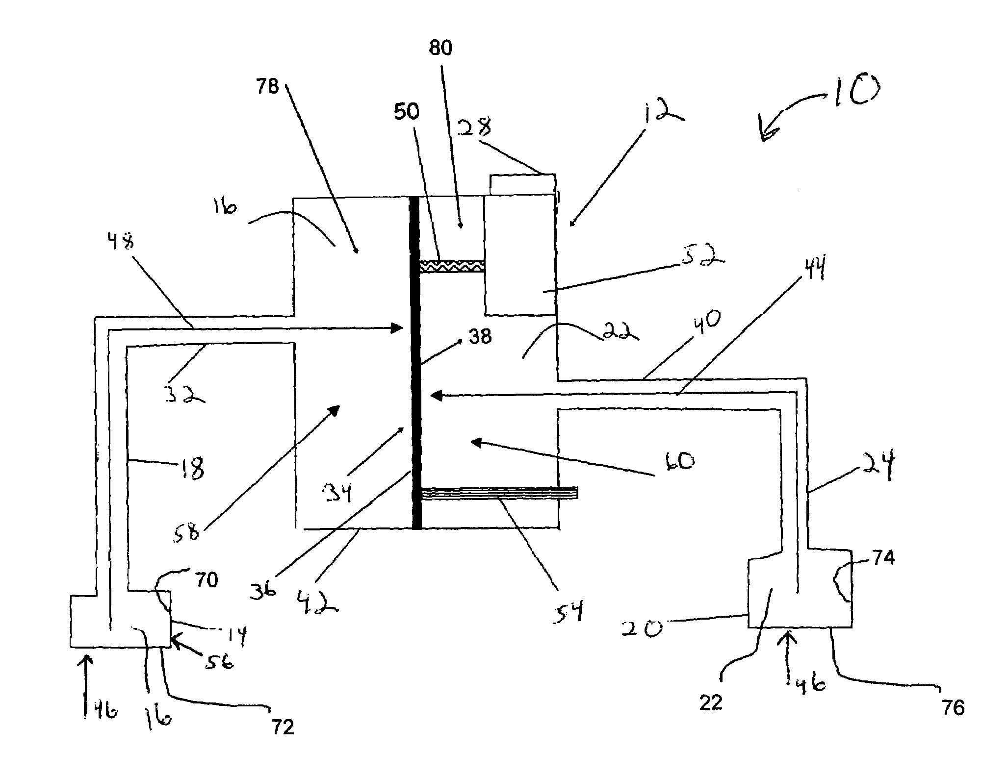
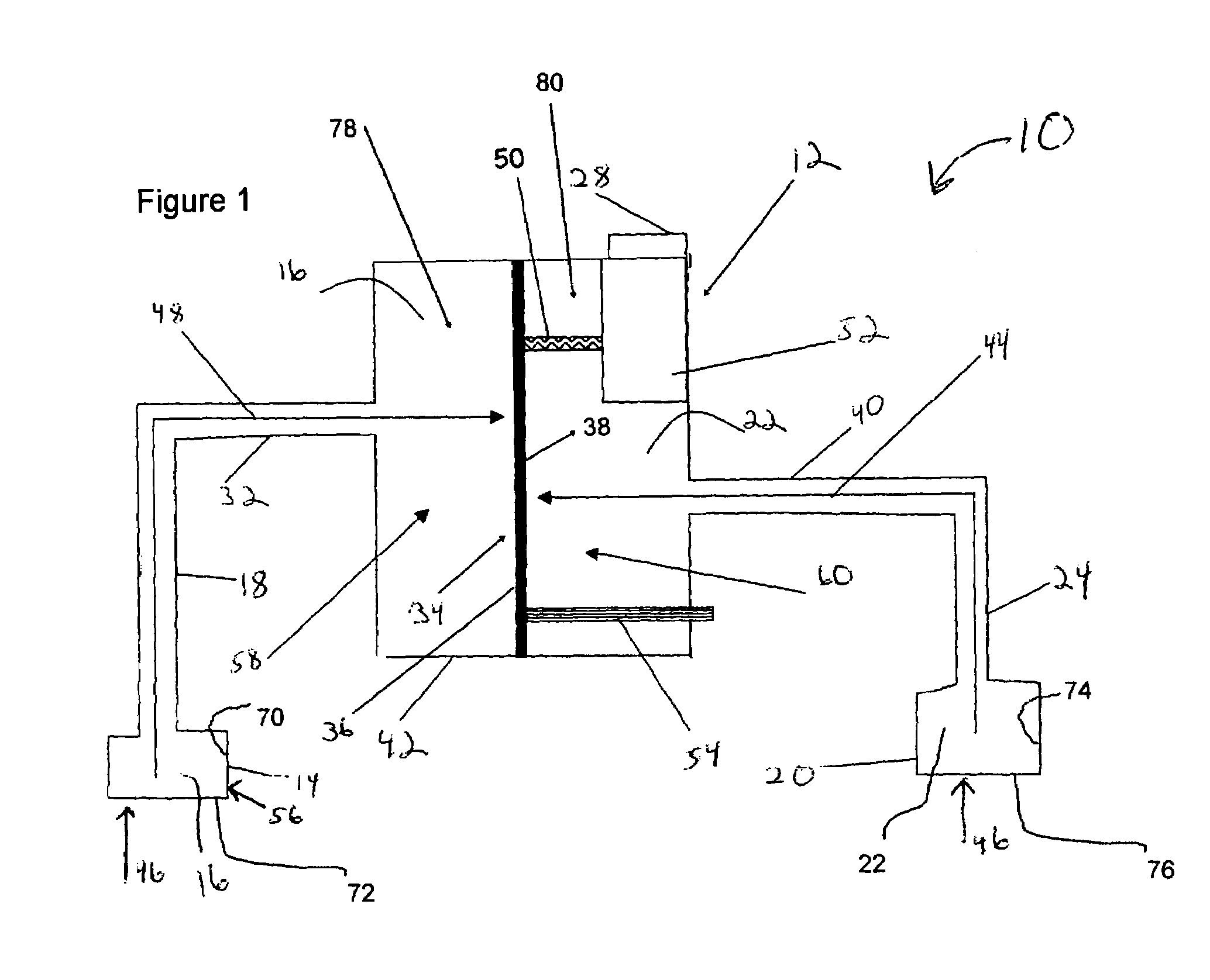
[0019]The present invention generally provides a tactile sensor which may be compensated against an external pressure, such as an ambient pressure at which the tactile sensor may be operated. In an embodiment, the present invention may be useful in environments which may apply an ambient pressure to the tactile sensor that may be above or below atmospheric pressure at sea level. Examples of such environments in which an embodiment of the present invention may be useful may include underwater environments such as those found on the underside of a marine vessel, on a submarine vessel, on an underwater robot, and the like. In an embodiment, the present inv...


PUM


Abstract

A tactile sensor comprises a sensing bladder in pneumatic communication with a first diaphragm side of a pneumatic diaphragm via a first fluid; the pneumatic diaphragm being actuatable by a displacement of the first fluid within the sensing bladder; the pneumatic diaphragm further comprising a second diaphragm side in fluid isolation from the first diaphragm side; the second diaphragm side being pneumatically biased against the first diaphragm side, and the second diaphragm side and the first diaphragm side of the pneumatic diaphragm each being in pneumatic communication with an external environment.

Description

GOVERNMENT RIGHTS[0001]The invention described herein may be manufactured and used by or for the Government of the United State of America for governmental purpose without payment of any royalties thereon or therefor.BACKGROUND OF THE INVENTION[0002]The present invention generally relates to a tactile sensor, and a method to tactilely sense, and more specifically, to a tactile sensor and method to tactilely sense which may not be affected by the application of pressure applied to the sensor by the environment in which the sensor may be located.[0003]The ability to sense touch may be of particular importance for tasks such as close-up assembly work, where vision may be obscured by objects, or may not be possible due to an absence of light or other conditions. Touch may by used to provide sensory feedback necessary for griping or sensing objects, determining the orientation of objects, and the like. Touch may be sensed using a tactile sensor. A tactile sensor may be incorporated on, f...

Claims


Application Information

Patent Timeline
IPC IPC(8): G01L1/02G01L5/08G01L7/00
CPCG01L13/025G01L1/02
Inventor FORD, KENNETHPRAY, JEFFERYRICHBURG, CHRISBERNSTEIN, CHARLES
Owner THE UNITED STATES OF AMERICA AS REPRESENTED BY THE SECRETARY OF THE NAVY
Why Eureka
Try Eureka