Emergency shelter structure

a shelter structure and emergency technology, applied in the direction of tents/canopies, building types, constructions, etc., can solve the problems of displaced families and families, and achieve the effect of strong frame and exceptional rigidity

Inactive Publication Date: 2006-02-28
GILLIS ROBERT E
View PDF36 Cites 18 Cited by
  • Summary
  • Abstract
  • Description
  • Claims
  • Application Information

AI Technical Summary

Benefits of technology

[0006]The present invention resides in a shelter structure which has a plurality of poles arranged in intersecting relationship and forming a plurality of pole crossings to form a frame. The frame has one or more four sided openings, each such opening having pole crossings as vertices and sections of said poles as sides thereof. Each of the poles has a first terminal end and a second terminal end, and each of the poles assumes a substantially arcuate shape under tension with its first and second terminal ends terminating in

Problems solved by technology

For example, in times of hurricane, flood, and other environmental disasters, entire families may be displaced from their homes.
Emergency relief and aid organizations often are challenged to find

Method used


Image

  • Emergency shelter structure
  • Emergency shelter structure
  • Emergency shelter structure

Examples


Embodiment Construction

[0012]Presently preferred embodiments of the invention will now be described in detail with reference to the drawings, wherein similar parts are identified by like reference numerals.

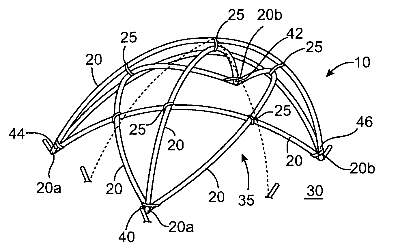
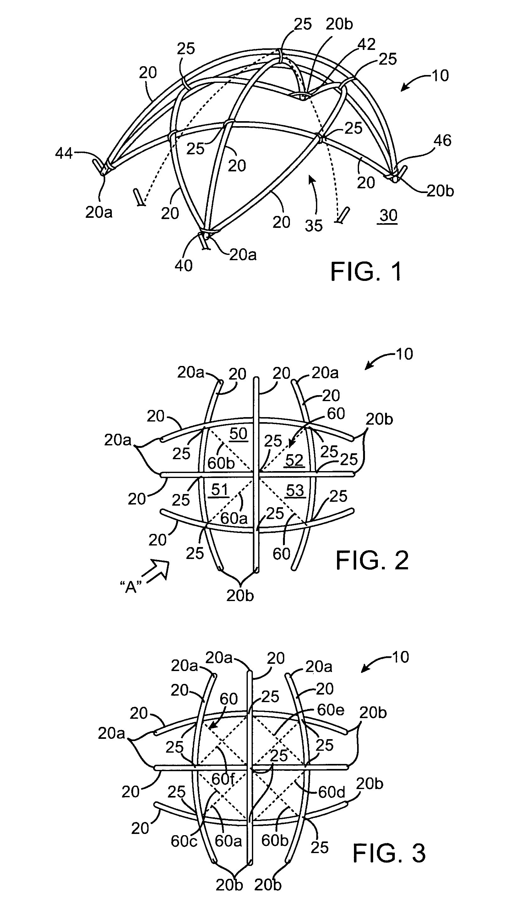
[0013]FIG. 1 illustrates a frame for a presently preferred form of shelter structure according to the invention. The frame 10 is formed by a plurality of flexible, resilient elongated poles 20, which are arranged in an intersecting pattern and which form a plurality of pole crossings 25. The poles 20 have opposite first and second terminal ends 20a, 20b, which terminate in a common plane 30, such as the ground or a base.

[0014]Under tension, the poles 20 flex in a generally arcuate shape, thereby defining a substantially dome-shaped frame having an interior volume 35. In the particular embodiment shown in FIG. 1, the terminal ends of three poles extending in a first direction are bound together and secured to the ground at 40 and 42, and the terminal ends of three other poles crossing in a second general...


PUM


Abstract

A shelter structure is disclosed having a substantially dome-shaped frame comprising a plurality of flexible resilient poles maintained under tension in substantially arcuate shape. The poles are arranged in intersecting relationship and form a plurality of pole crossings. Opposite ends of the poles terminate in a common plane such as the ground or a base. The pole arrangement creates a plurality of adjacent four-sided openings having pole crossings as vertices and sections of poles as sides. A plurality of tension harnesses interconnect diagonal vertices of adjacent openings, thereby providing strength and rigidity to the structure. The frame defines an interior volume and a membrane or covering is connected to the frame to substantially shelter the interior volume.

Description

BACKGROUND OF THE INVENTION[0001]This invention relates to flexible shelter structures such as tents and the like.[0002]Numerous flexible shelter and tent structures are described in the prior art. For example, various convex multi-poled tent structures are described in U.S. Pat. Nos. 3,986,519, 4,099,533, 4,265,260, 4,414,993, and 6,145,527, all of which are owned by the inventor of the present invention. U.S. Pat. Nos. 3,986,519 and 4,099,533 both disclose dome-like structures composed of a plurality of flexible pole or rod elements maintained under tension in a generally arcuate shape, and an underlying membrane. Each structure includes at least two intersecting sets of such pole or rod elements. The rod or pole elements are held in fixed relationship at intersections by fittings secured to the underlying flexible membrane or sheath. The underlying membrane or sheath acts as a tension member to maintain the poles under tension.[0003]U.S. Pat. Nos. 4,265,260 and 4,414,993 disclose...

Claims


Application Information

Patent Timeline
IPC IPC(8): E04H15/36E04H15/40
CPCE04H15/40Y10S135/906
Inventor GILLIS, ROBERT E.
Owner GILLIS ROBERT E
Why Eureka
Try Eureka