Self-aligning hitch assembly

a self-aligning and self-sealing technology, applied in the direction of towing devices, vehicle components, transportation and packaging, etc., can solve the problems of increasing the amount of time spent aligning the hitch, affecting the towing vehicle driver, and affecting the alignment

a self-aligning and self-sealing technology, applied in the direction of towing devices, vehicle components, transportation and packaging, etc., can solve the problems of increasing the amount of time spent aligning the hitch, affecting the towing vehicle driver, and affecting the alignment

US7004488B2Inactive Publication Date: 2006-02-28NEW DESIGNS CORP

Image

  • Self-aligning hitch assembly
  • Self-aligning hitch assembly
  • Self-aligning hitch assembly

Examples


Embodiment Construction

[0032]The following description of one illustrative embodiment of the present invention is not intended to limit the scope of the invention. It will be understood that many substantially equivalent arrangements and / or components may be substituted for those depicted in connection with this one illustrative embodiment.

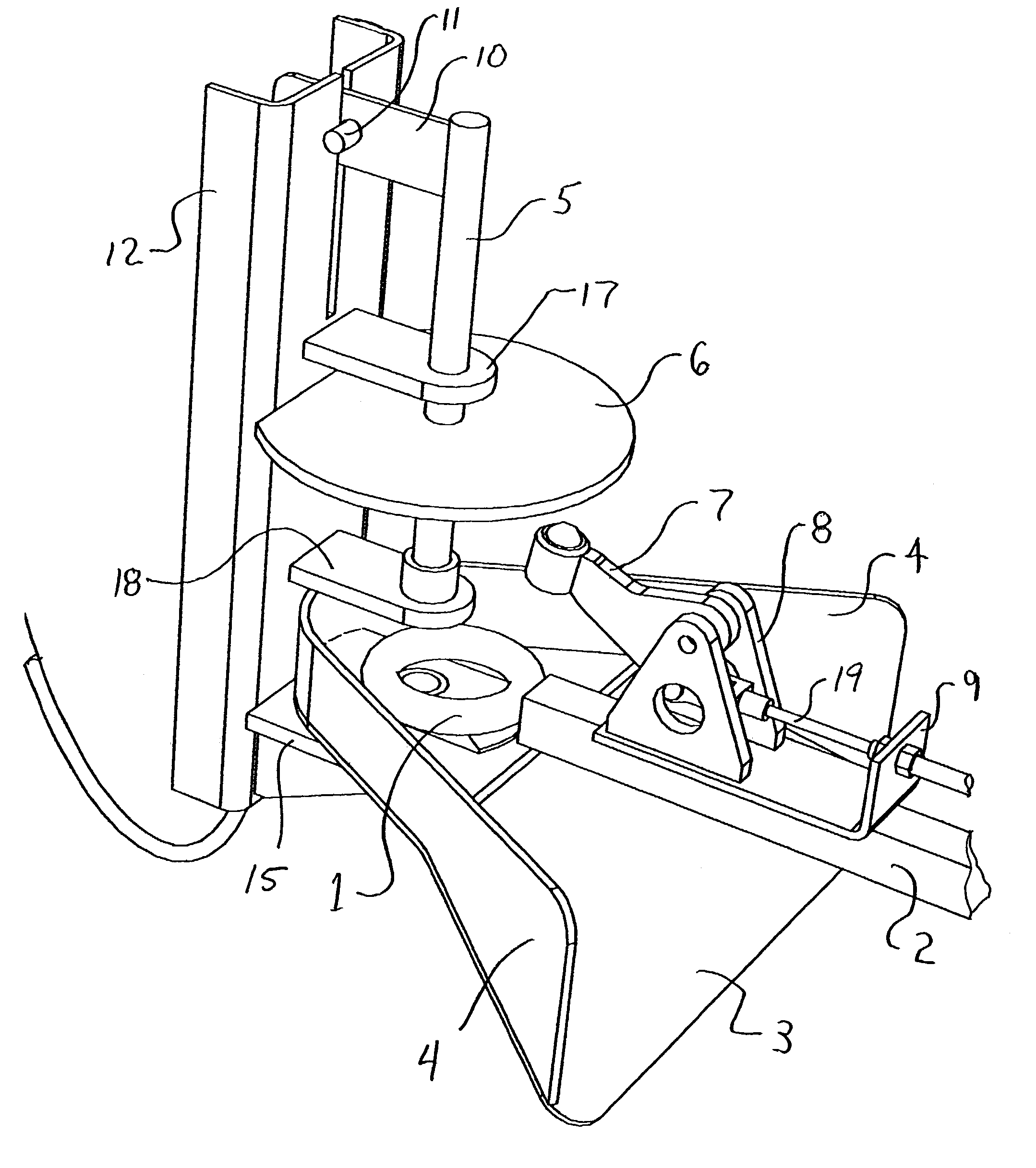
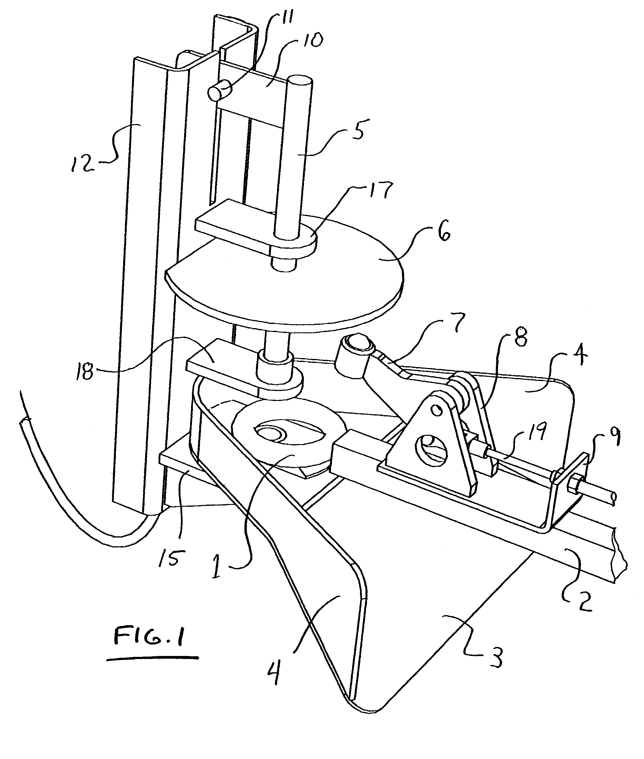
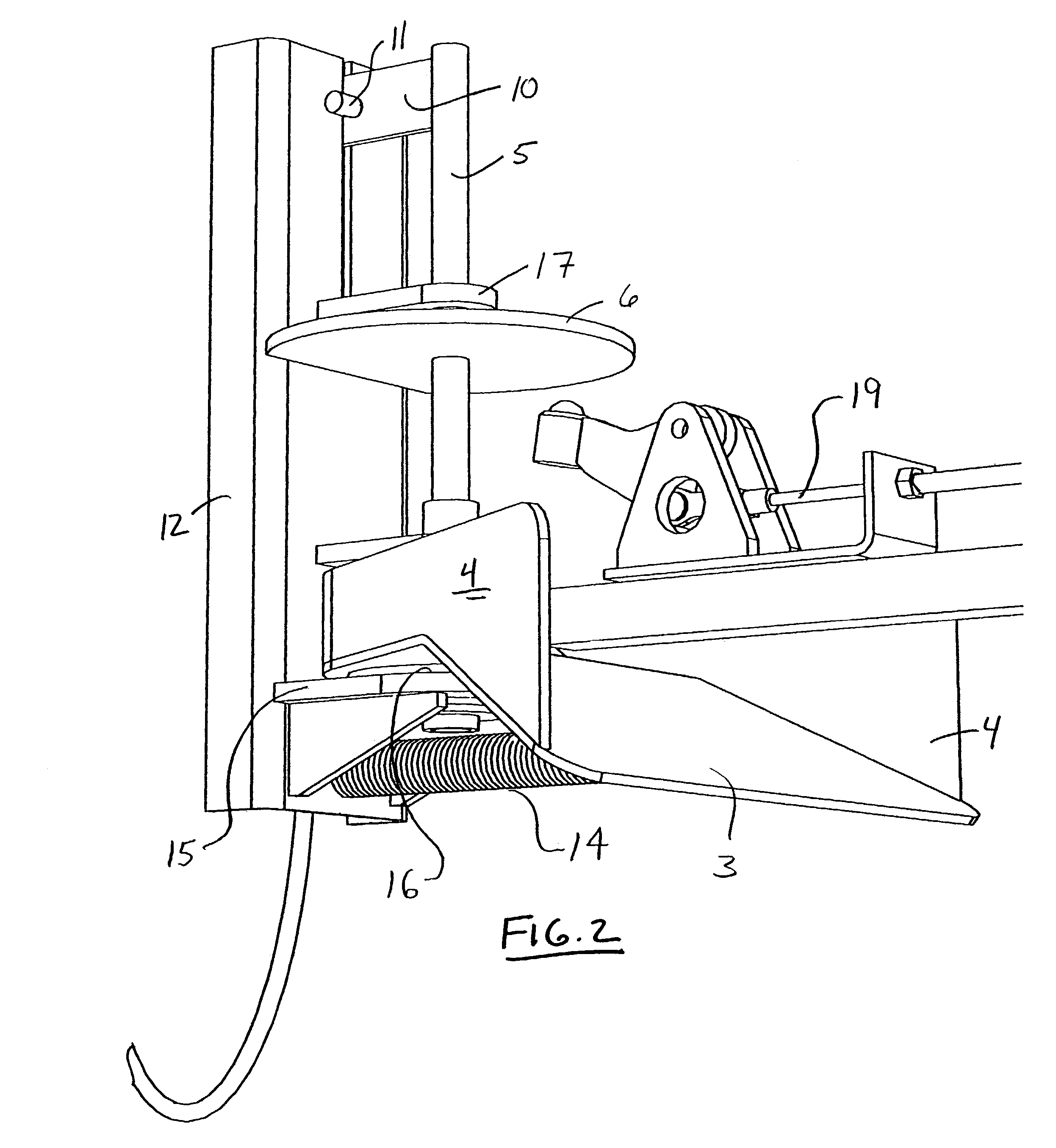
[0033]The following parts of the illustrative hitch assembly may be found in the figures:

[0034]

Part No.Part Name1Tongue Eye2Trailer Tongue3Ramp4Edge Guide5Plunger6Plunger Plate7Brake Arm8Mount Brackets9Brake Cable Mount10Plunger cable Attachment11Dowel12Main Frame13Control Cable Mount14Alignment Spring15Base Plate16Thrust Washer17Guide Plate18Guide Plate with Bushing19Trailer Brake Cable20Control Cable

[0035]Initial setup would involve the installation of the hitch assembly onto the towing vehicle so the lowest edge of the ramp is at a predetermined elevation. The trailer tongue, while disconnected from the towing vehicle will need to be positioned so the bottom surface ...


PUM


Abstract

Apparatus and methods for hitching and unhitching of trailers or other towed devices are disclosed. The hitch assemblies may include alignment features to correct for errors in alignment of the hitch and trailer tongue during the hitching process. The hitch assemblies may compensate for vertical as well as horizontal misalignment. In addition, the hitch assemblies may include automated capture and release of the tongue on the hitch. The hitch assemblies may also disengage integral braking systems that are present on the trailer during the hitching process and re-engage the brakes after unhitching. All of these operations may be accomplished without requiring the driver of the towing vehicle to leave the driving position.

Description

RELATED APPLICATIONS[0001]This application claims the benefit under 35 U.S.C. § 119 of U.S. Provisional Patent Application No. 60 / 356,904 filed on 12 Feb. 2002, which is hereby incorporated by reference in its entirety.FIELD OF THE INVENTION[0002]The present invention relates to the field of self-aligning and self securing hitch assemblies.BACKGROUND[0003]The hitching and unhitching of trailers or other towed devices presents problems for drivers of the towing vehicles. In most instances, the drivers must mount and dismount the towing vehicle during each hook-up procedure to view the alignment of the hitch and tongue several times during the process. The problems may be exacerbated when the towed vehicles incorporate brakes that must be disengaged after the tongue on the towed device is secured to the hitch of the towing vehicle. Disengagement of the brake may require the driver to dismount the towing vehicle one additional time before proceeding with the trailer.[0004]Unhitching of...

Claims


Application Information

Patent Timeline
28 Feb 2006
Publication
US7004488B2
IPC
B60D1/00; B60D1/02; B60D1/36
CPC
B60D1/02; B60D1/363; B60D1/242
Inventors
REITER, WILLIAM P.; KOVASH, DEAN A.