System and method for capturing and releasing fixed-wing aircraft

a fixed-wing aircraft and flight system technology, applied in the field of aircraft, can solve the problems of large space requirements of runways and airports, large cost of urban centers, and large space requirements of rotary-wing aircraft, and achieve the effects of reducing the cost of landing and landing

Active Publication Date: 2019-10-31
PINTO RYAN EVARISTO
View PDF9 Cites 15 Cited by
  • Summary
  • Abstract
  • Description
  • Claims
  • Application Information

AI Technical Summary

Benefits of technology

[0013]The capture-and-release aircraft further can comprise a cargo container secured to the frame, and each of the aircraft engagement members can further comprise at least one motor that, when the anchor-capture devices are coupled to the anchors of the fixed-wing aircraft, can move the cargo container between a first position in which the cargo container is spaced from the fixed-wing aircraft and a second position in which the cargo container is adjacent the fixed-wing aircraft.

Problems solved by technology

These runways tend to require significant space, as they have to be sufficiently long to enable the fixed-wing aircraft to achieve sufficient speed and, thus, lift, and to permit sufficient distance to touch down, decelerate, and stop the aircraft.
As a result, such runways and airports are built outside of urban centers or occupy very expensive land within urban centers.
These two design objectives are often in direct conflict with each other, which is why it's generally infeasible to design a vertical take-off and landing (“VTOL”) aircraft that simultaneously is fuel efficient, has a long range, can travel at very high velocities, and carry heavy loads, all while keeping the design simple and build costs low.
As a result, rotary-wing aircraft require relatively small takeoff and landing space compared to fixed-wing aircraft as they can take off substantially vertically.
Rotary-wing aircraft, however, cannot generally achieve the same speeds, range, and payload capacities as possible with fixed-wing aircraft.

Method used


Image

  • System and method for capturing and releasing fixed-wing aircraft
  • System and method for capturing and releasing fixed-wing aircraft
  • System and method for capturing and releasing fixed-wing aircraft

Examples


Embodiment Construction

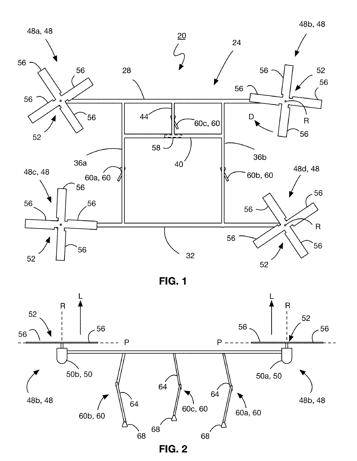
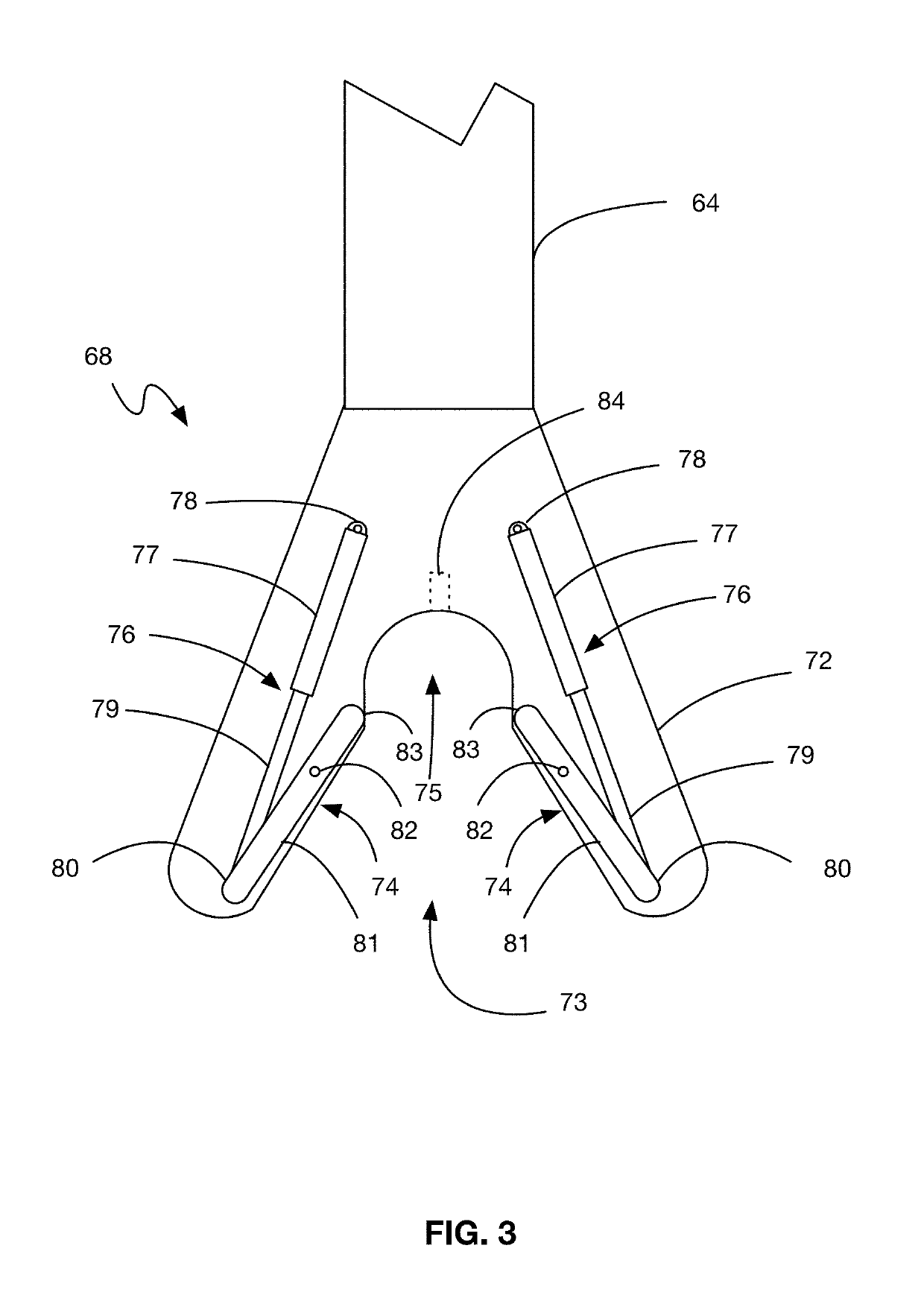
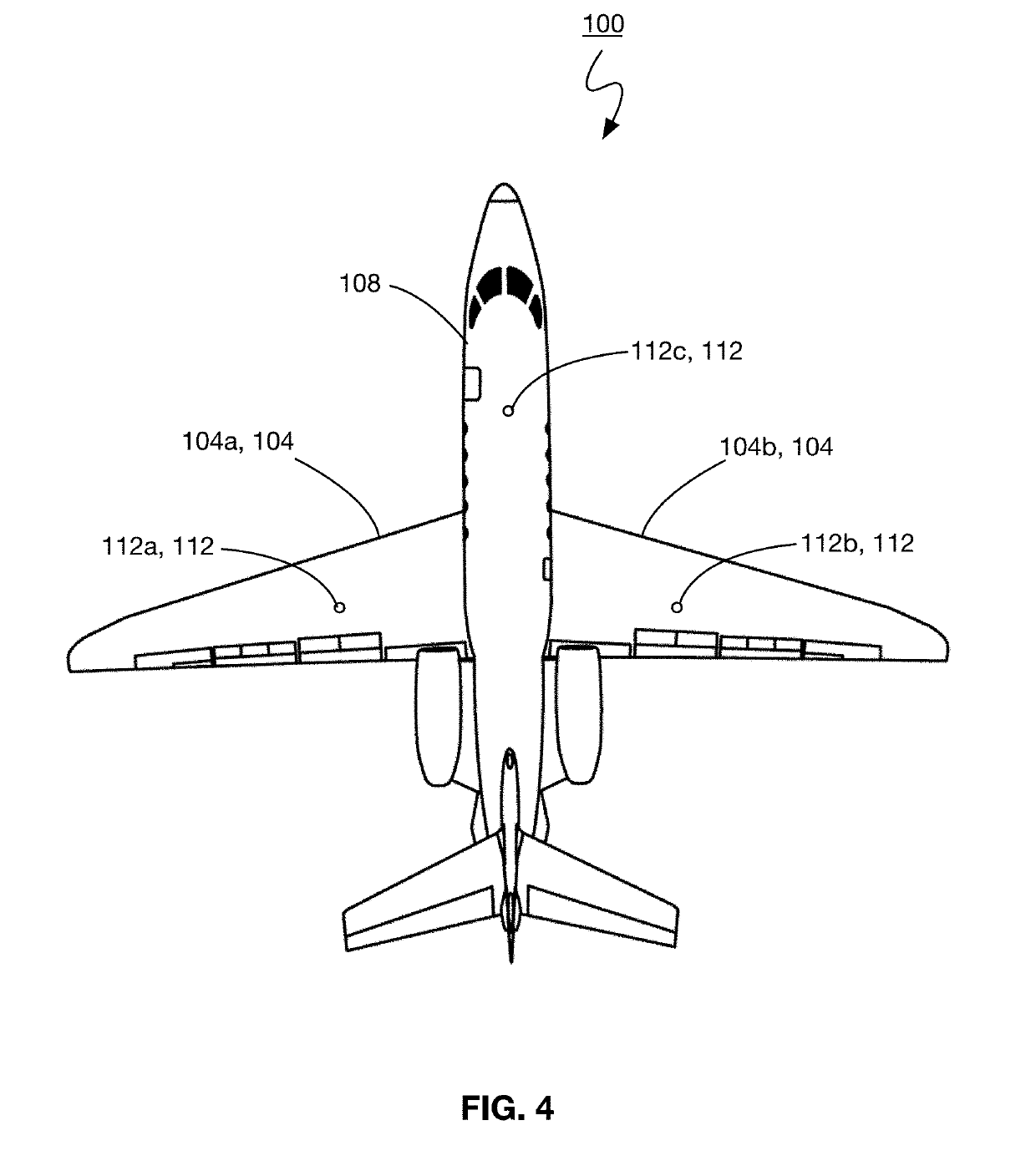
[0030]For simplicity and clarity of illustration, where considered appropriate, reference numerals may be repeated among the Figures to indicate corresponding or analogous elements. In addition, numerous specific details are set forth in order to provide a thorough understanding of the embodiments described herein. However, it will be understood by those of ordinary skill in the art that the embodiments described herein may be practiced without these specific details. In other instances, well-known methods, procedures and components have not been described in detail so as not to obscure the embodiments described herein. Also, the description is not to be considered as limiting the scope of the embodiments described herein.

[0031]Various terms used throughout the present description may be read and understood as follows, unless the context indicates otherwise: “or” as used throughout is inclusive, as though written “and / or”; singular articles and pronouns as used throughout include th...


PUM


Abstract

A capture-and-release aircraft for capturing and releasing fixed-wing aircraft is provided. The capture-and-release aircraft comprises a frame to which is secured a set of rotor units. Each rotor unit has a rotor with a rotation axis, the rotation axes of the rotors being generally parallel. A set of aircraft engagement members is also secured to the frame that can align with a set of anchors of a fixed-wing aircraft to releasably couple with the anchors.

Description

CROSS-REFERENCE TO RELATED APPLICATIONS[0001]This application is a National Stage of International Application No. PCT / CA2017 / 051495, filed Dec. 11, 2017, which claims the benefit of U.S. Provisional Application No. 62 / 433,623, filed Dec. 13, 2016, the contents of both of which are incorporated herein by reference in their entirety.FIELD[0002]The following relates generally to aircraft. In particular, the following relates to a system and method for capturing and releasing fixed-wing aircraft.BACKGROUND OF THE DISCLOSURE[0003]Fixed-wing aircraft are capable of flight using wings that generate lift caused by the rapid travel of air over the fixed wings. The fixed wings have an airfoil shape, causing the air pressure on the top of the wing to be reduced relative to the air pressure on the bottom of the wing when air travels above and below the fixed wings in a general direction, resulting in lift. In order to cause air to travel above and below the fixed wings to generate sufficient l...

Claims


Application Information

Patent Timeline
Patent Type & Authority Applications(United States)
IPC IPC(8): B64D5/00B64D9/00
CPCB64D5/00B64C37/02B64C2201/082B64C2201/108B64C2201/027B64D9/00B64C27/20B64D39/00B64U10/13B64U30/20B64U70/20
Inventor PINTO, RYAN EVARISTO
Owner PINTO RYAN EVARISTO
Why Eureka
Try Eureka