Methods and apparatus for forming concrete structures

Inactive Publication Date: 2006-02-28
RUSSELL MATTHEW
View PDF8 Cites 19 Cited by
  • Summary
  • Abstract
  • Description
  • Claims
  • Application Information

AI Technical Summary

Benefits of technology

[0015]What is needed then is a method of, and apparatus for, constructing vertical or near-vertical concrete structures which achieves the benef

Problems solved by technology

However, relatively tall open-form and combination-form structures are not addressed by slip-forming or jump-forming, and are not economical with conventional forming methods except as they are done in a “relatively short” format.
This means that these types of relatively tall, open-form structures are not currently produced in a systematic or machine-like fashion, as are relatively tall closed-form structures.
Specifically: (1) Vertical segmental construction is not addressed by jump-form or slip-form methods of construction; (2) although segmental construction is addressed by conventional means, only relatively short structures can be economically effected by conventional means (i.e., conventional forming methods of construction are not economically adaptable for construction of tall, closed-form or open-form structures); (3) although accurate geometric measurement is possible with all methods of construction given modern surveying equipment, accurate geometric control is not inherently achievable for relatively tall and / or large footprint structures constructed with the current jump-form or slip-form methods of construction; (4) modern jump-forming and slip-forming techniques are very labor intensive; (5) none of the three concrete forming methods described above (jump-forming, slip-forming, and conventional forming) are readily adaptable to both discrete and continuous forming; (6) the methods by which jump-forms, slip-forms, and conventional forms are borne by the evolving structure is cumbersome to productivity; (7) in all three forming methods there are significant limitations on geometries due to the method of resolution of the hydrostatic force of the concrete between the inside and outside forms; and (8) jump-forming inherently does not allow for a work deck on the outer ring of forms.
The reason why conventional forms are not readily adaptable for construction of tall, open-form structures is inherent in the method: the process of loosening the forms from the wall-ties or through-bolts, lifting the forms vertically to the next level, and attaching the wall-ties or installing the through-bolts is a very cumbersome, labor intensive operation.
None of the prior art methods of constructing concrete structures address both discrete and continuous modes of operation in the vertical or near vertical direction.
Jump-forms are not designed, nor are they readily adaptable for, slip (continuous) forming.
Slip-forms are not designed, nor are they readily adaptable for, discrete forming.
Although discrete forming with slip-forms may be an inadvertent result of stopping the slip form operation and letting the concrete set-up, it is not an intended function, nor is it a simple matter to get a slip-form moving again when the concrete sticks solidly to the forms.
They cannot be readily transitioned for use in a bi-model fashion.
Slip forms, though relatively failsafe in the sense that the support pipes are continuously buried in the wall, are inherently cumbersome for placing rebar and concrete because the pipe and yoke system repeats itself so frequently around the perimeter.
Because of this, structures with dense rebar and / or large perimeters are impractical with slip-forming.
This “tie-through” method of resolving the hydrostatic forces from the concrete and attaching the forms to the concrete is cumbersome to upward progression because of the labor-intensive process of removing and re-inserting bolts or ties.
There are a number of shortcomings with the prior-art chord-form method: (1) As with the classical jump-form method which relies on the hoop tensile capacity of the forms to resolve the hydrostatic forces from the concrete, there is a practical limitation on both the geometry and maximum diameter which can be achieved.
A 60′ radius curve is the practical limit for using these types of forms; (2) As with jump-forming, the chord-form method requires two or more levels of forms, and it requires that these forms be “jumped”, a very labor intensive process; (3) The chord-form method requires heavy buttress trusses at both ends for the full height of the segment being constructed.
The capital and mobilization costs associated with these trusses are very high and set-up times are long, especially for very tall segments; (4) Vertical alignment of the segment can only be achieved when each new buttress truss is installed, and only to the degree to which the truss can be tilted out of plumb to correct the alignment.

Method used


Image

  • Methods and apparatus for forming concrete structures
  • Methods and apparatus for forming concrete structures
  • Methods and apparatus for forming concrete structures

Examples


Embodiment Construction

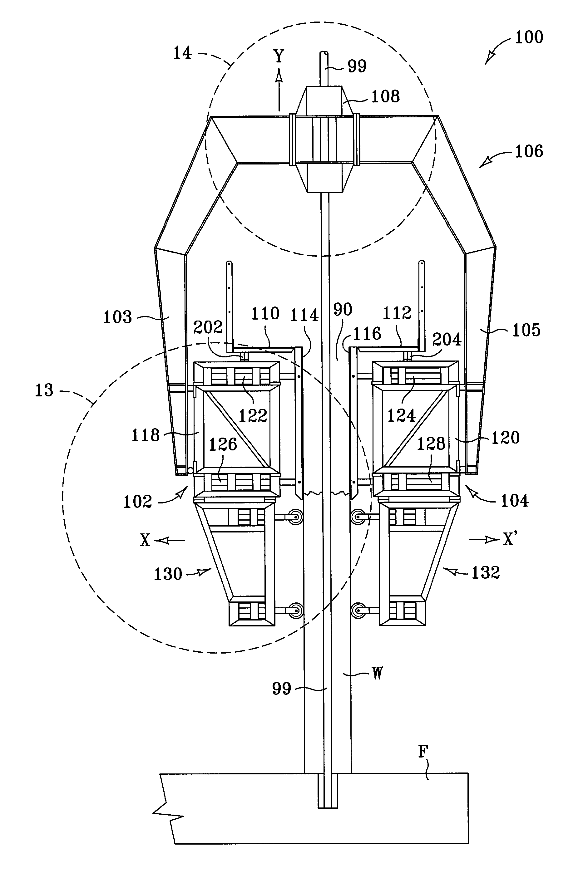
[0049]The invention provides for methods and apparatus useful for construction of vertical and near-vertical concrete structures. The apparatus allows for such structures to be formed in either a slip-form type casting mode, a jump-form type casting mode, or a combination of these modes. The apparatus can be used to produce vertical and near-vertical concrete structures in a segmental-type casting mode, as well as in a monolithic casting mode. The apparatus of the present invention may from time-to-time be referred to herein as a “jump-slip machine” since it can be used to perform both of these prior art methods of forming concrete structures. The term “jump-slip machine” is appropriate since the apparatus can cast vertical or near vertical reinforced concrete segments, or whole structures, in either a discrete (jump) or continuous (slip) mode. The methods and apparatus of the present invention are particularly useful for forming any size of closed-form, open-form, or combination-fo...


PUM

PropertyMeasurementUnit
Lengthaaaaaaaaaa
Flexibilityaaaaaaaaaa

Abstract

An apparatus for forming concrete structures includes a first truss module and a second truss module, as well as a first and a second concrete form. The apparatus further includes a first and a second actuator device. Each first and second actuator device is mounted on the respective first and second truss module, and each first and second actuator device can move the respective first and second form translationally with respect to the respective first and second truss module. A yoke connects the first truss module to the second truss module to thereby place the concrete forms in generally parallel, spaced-apart relationship. A climbing device attached to the yoke can engage a climb rod and can move the apparatus upward along the climb rod.

Description

CROSS REFERENCE TO RELATED APPLICATIONS[0001]The present invention claims priority under 35 U.S.C. §120 to U.S. Provisional Patent Application Ser. No. 60 / 313,538, filed Aug. 20, 2001 and hereby incorporated herein by reference in its entirety.FIELD OF THE INVENTION[0002]The invention claimed and disclosed herein pertains to apparatus and methods for forming concrete structures, and in particular to methods and apparatus for forming vertical or near-vertical concrete structures.BACKGROUND OF THE INVENTION[0003]This invention pertains to methods and apparatus for constructing vertically, oriented, or near-vertical, concrete structures. “Near-vertical” means that the structure, or segments of whole structures, can be purposely constructed at a slope (or “out-of-plumb”, which is not to be confused with construction plumbness tolerances), tapered (so that an inside or outside surface is not plumb), curved in vertical section (for example, as in a cooling tower structure), or a combinati...

Claims


Application Information

Patent Timeline
IPC IPC(8): E04G11/04E04G11/20E04B1/34E04B1/35E04G11/22E04H12/12
CPCE04B1/3404E04H12/12E04G11/22E04B2001/3588E04G17/002
Inventor RUSSELL, MATTHEW
Owner RUSSELL MATTHEW
Why Eureka
Try Eureka