
Powerpole connector assembly and methods thereof

a technology of powerpole connectors and components, applied in the direction of electrical apparatus, connection, coupling device connection, etc., can solve the problems of difficult and expensive assembly of this device, etc., and achieve the effect of easy assembly and maintenance, easy training, and easy attachment and secur

Active Publication Date: 2006-02-28
ANDERSON POWER PRODS
View PDF6 Cites 39 Cited by
  • Summary
  • Abstract
  • Description
  • Claims
  • Application Information

AI Technical Summary

Benefits of technology

[0009]The present invention provides a powerpole connector assembly that is easier to assemble and maintain then prior powerpole connector assemblies and also provides positive latching, strain relief, and system grounding. The powerpole connectors can easily be attached and secured in the housing in a variety of configurations without the need to align and pass retaining pins through holes in the housing. Additionally, the housing provides enough space for easily training of larger gauge cables though the housing. Further, this powerpole connector assembly is compatible and mateable with existing powerpole connectors.

Problems solved by technology

Unfortunately, there are a number of shortcomings to this method of making and design of the powerpole connector assembly 10.
As the discussion above illustrates, the process for making this powerpole connector assembly 10 is very labor intensive and time consuming.
These and other factors make the assembly of this device difficult and expensive.
In addition to the difficulties in making the powerpole connector assembly 10, the components used in making the powerpole connector housing 14 can also be difficult to manufacture.
This also adds to the overall cost to manufacture this types of prior powerpole connector assembly 10.

Method used


Image

  • Powerpole connector assembly and methods thereof
  • Powerpole connector assembly and methods thereof
  • Powerpole connector assembly and methods thereof

Examples


Embodiment Construction

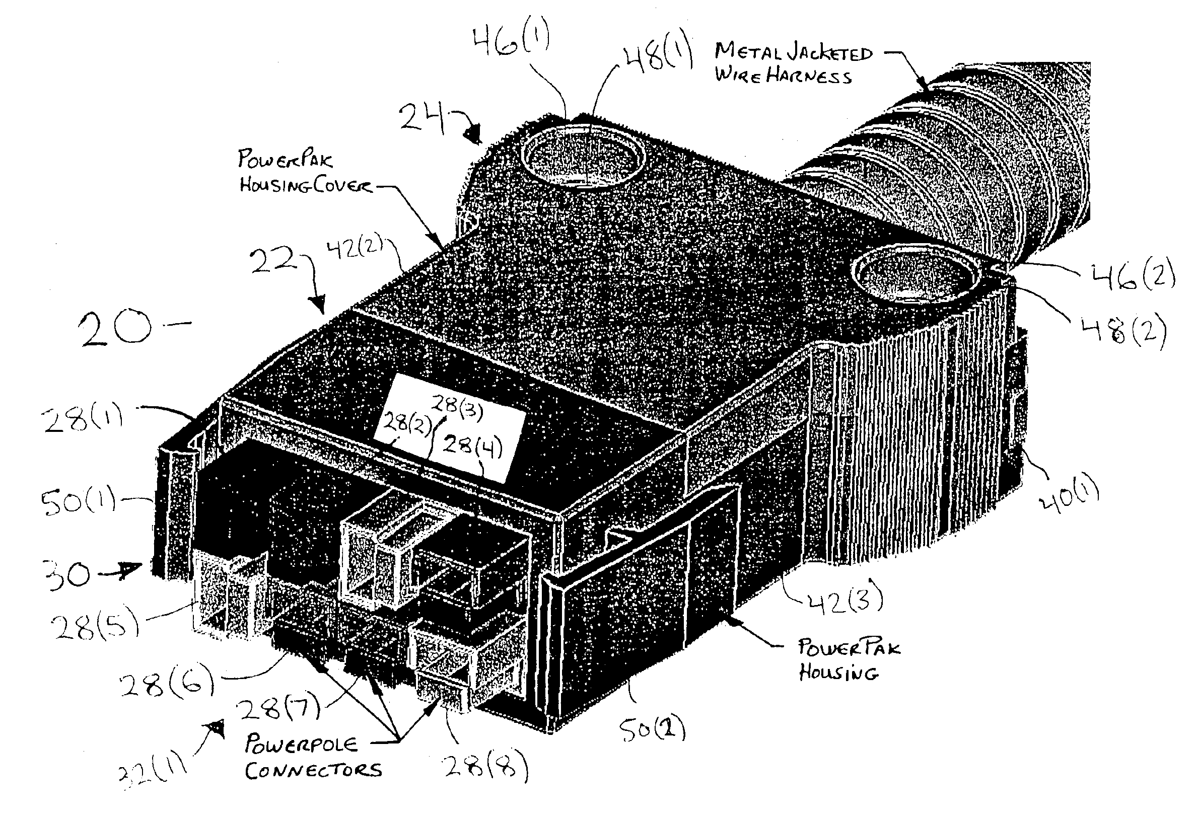
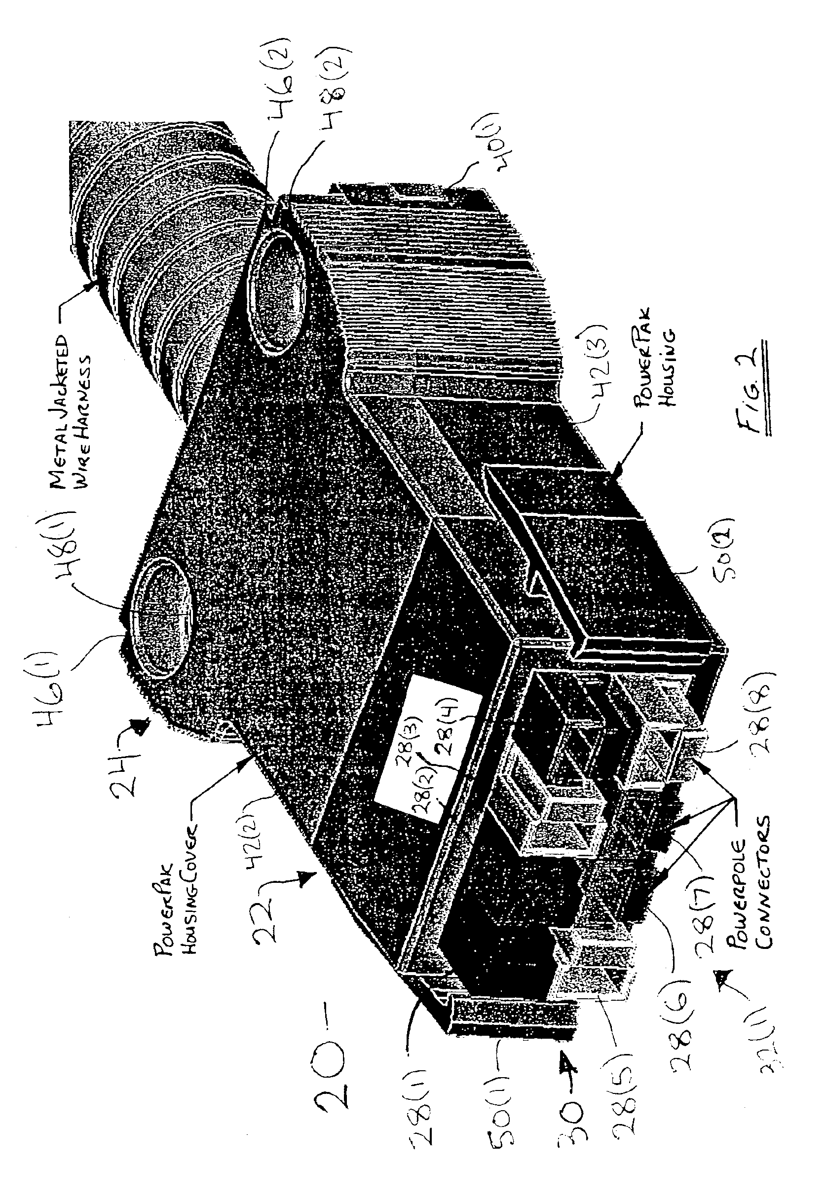
[0027]A connector assembly 20 in accordance with embodiments of the present invention is illustrated in FIGS. 2-11C. The connector assembly 20 includes a housing 22, a cover 24, and a cable clamp 26 for mating with and retaining connectors 28(1)-28(8), although the connector assembly can comprise other types and numbers of components connected in other manners. The present invention provides a connector assembly 20 that is easy and inexpensive to use and maintain and which also provides positive latching, strain relief, and system grounding.

[0028]Referring more specifically to FIGS. 2-5, 7, 8, the housing 22 is a molded plastic component, although other types of materials can be used to make the housing 22, such as metal, depending on the structural and electrical requirements of the application. The housing 22 defines a passage 30 which has first and second openings 32(1) and 32(2), although the housing 22 could have other numbers of passages and openings. The first opening 32(1) o...


PUM


Abstract

A connector assembly includes a housing and at least one connector. The housing which defines a passage with first and second openings and which has at least one inner surface with at least one of a groove. The connector has at least one outer surface with at least one projection. The projection detachably mates with the groove to secure the connector in the passage in the housing adjacent the first opening in one of a variety of configurations.

Description

[0001]This application claims the benefit of U.S. Provisional Patent Application Ser. No. 60 / 493,422 filed Aug. 7, 2003 which is hereby incorporated by reference in its entirety.FIELD OF THE INVENTION[0002]The present invention relates generally to electrical connectors and, more particularly, to a powerpole connector housing for the packaging of blocked powerpole connectors into a housing which provides positive latching, strain relief, and system grounding.BACKGROUND[0003]Referring to FIG. 1, an example of making a prior power powerpole connector assembly 10 is illustrated. In this example, an end user must thread the cables 12(1)-12(8) through the housing 14, attach the powerpole connectors 16(1)-16(8) to the ends of each of the cables 12(1)-12(8), and then pull the powerpole connectors 16(1)-16(8) back into the housing 14. Once in the powerpole connectors 16(1)-16(8) are in place in the housing 14, the end user must lock the powerpole connectors 16(1)-16(8) into the housing 14 b...

Claims


Application Information

Patent Timeline
Patent Type & Authority Patents(United States)
IPC IPC(8): H01R13/502H01R13/518H01R13/58
CPCH01R13/582H01R13/518
Inventor MANCINI, DANNA A.BAKER, CRAIG H.BEAUPRE, ANDRE G.NAGER, URS F.
Owner ANDERSON POWER PRODS
Learn More