
Dual operational frequency slot antenna

Inactive Publication Date: 2006-02-28
TATUNG UNIVERSITY +1
View PDF6 Cites 39 Cited by
  • Summary
  • Abstract
  • Description
  • Claims
  • Application Information

AI Technical Summary

Benefits of technology

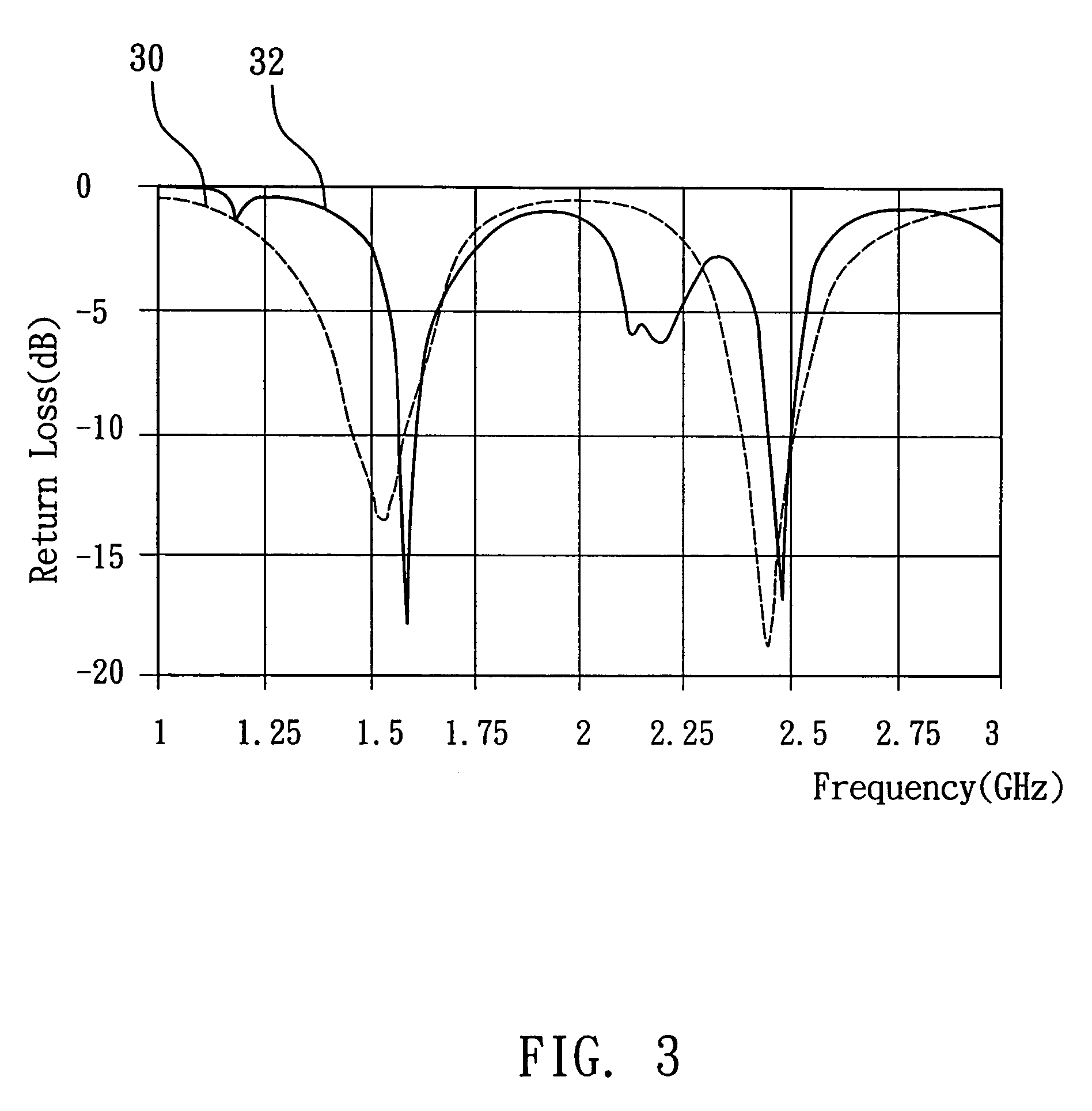
The present invention is a slot antenna that can transmit and receive circularly polarized signals at two different frequencies. It consists of two L-type slot antennas connected by a metal feed line. This allows the antenna to work at both frequencies simultaneously. The technical effect of this invention is the ability to transmit and receive wireless signals from a satellite or in an RFID system with a single antenna.

Problems solved by technology

However, the above-mentioned technologies only operate at a single frequency.

Method used


Image

  • Dual operational frequency slot antenna
  • Dual operational frequency slot antenna
  • Dual operational frequency slot antenna

Examples


Embodiment Construction

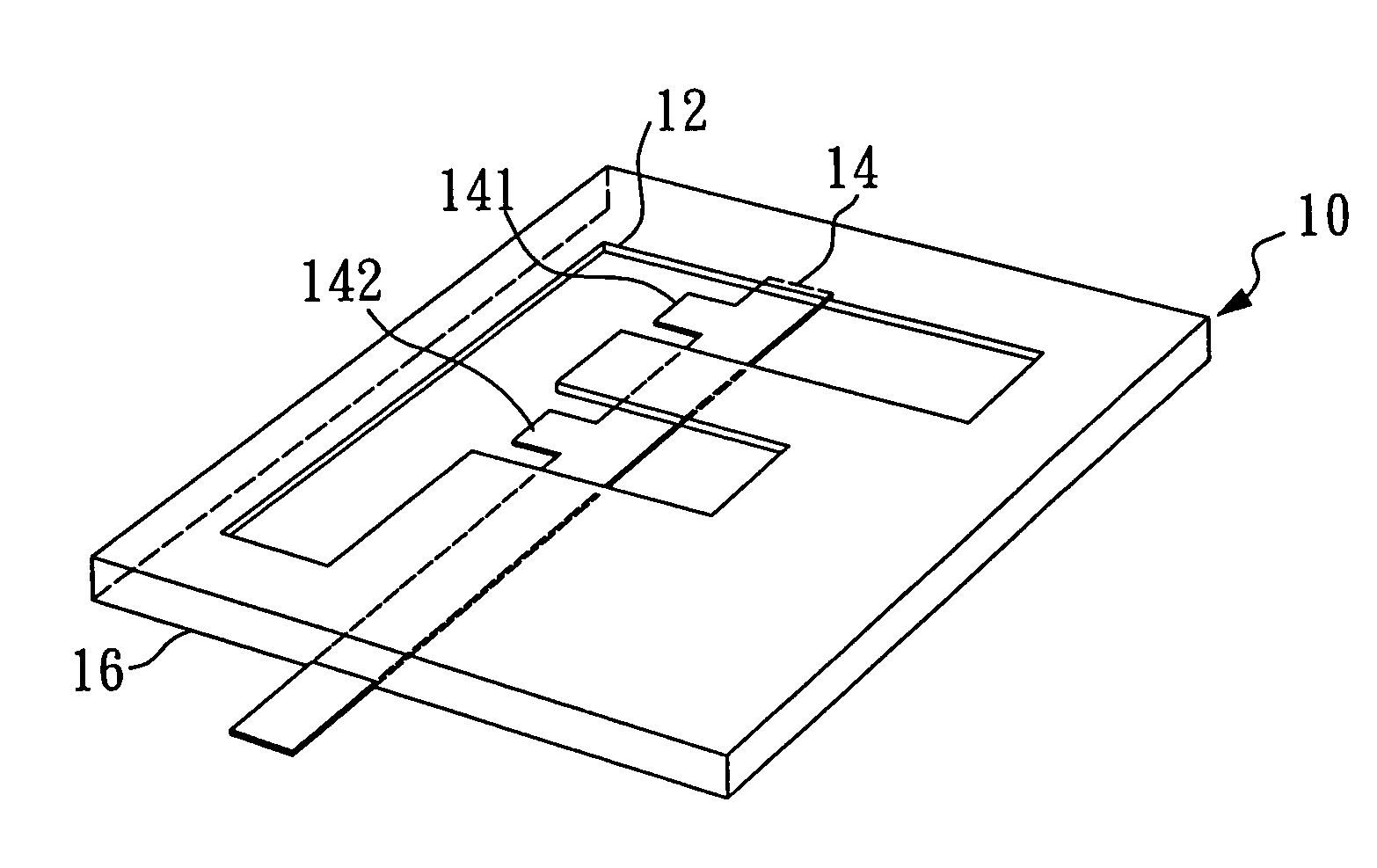
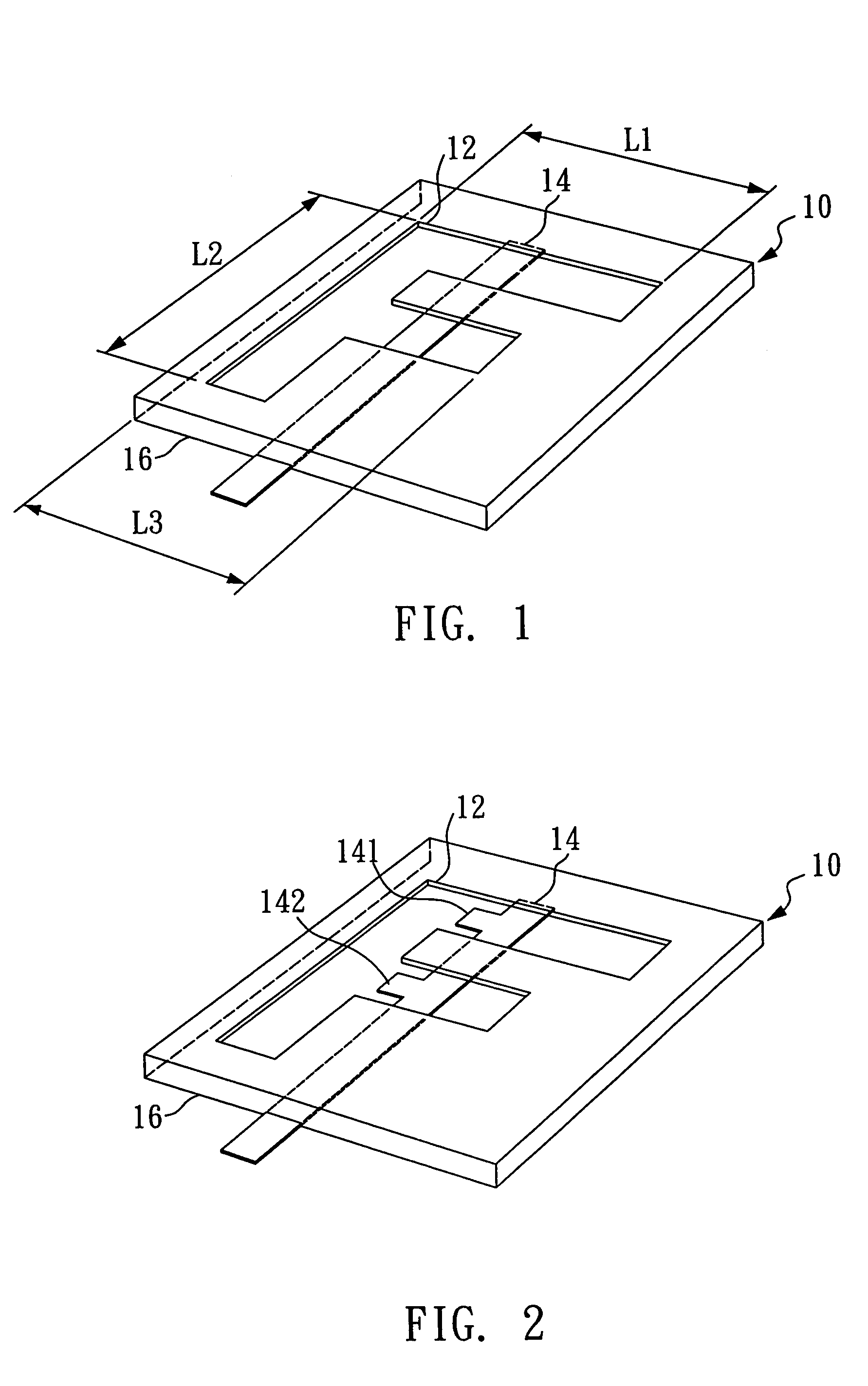
[0014]A dual operational frequency slot antenna 10 of the present invention comprises a slot antenna and a feed line. The slot antenna is adapted to receive circularly polarized radiation at different frequencies and transmit circularly polarized radiation to the free space. The size of the slot antenna and the feed line are small, therefore the size of the dual operational frequency slot antenna 10 is decreased.

[0015]FIG. 1 is a schematic drawing of the dual operational frequency slot antenna 10. The dual operational frequencies slot antenna 10 comprises:

[0016]an F-type slot antenna 12 which is composed of two L-type slot antennas; each L-type slot antenna is adapted to receive and transmit circularly polarized radiation at a single frequency. Therefore, the F-type slot antenna 12 can transmit and receive two different frequencies of circularly polarized radiation. As shown in the drawing, the F-type slot antenna 12 can be divided into three sections: L1 (for example, 0.029 m in le...


PUM


Abstract

A dual operational frequency slot antenna for receiving / transmitting wireless signals from a satellite or for receiving / transmitting wireless signals in an RFID system comprises two L-type slot antennas and a printed circuit feed line to receive and transmit circularly polarized radiation at dual operational frequencies.

Description

BACKGROUND OF THE INVENTION[0001]1. Field of the Invention[0002]The present invention relates to a slot antenna and, more particularly, to a dual operational frequency slot antenna for receiving and transmitting at dual operational frequencies using a circularly polarized wave.[0003]2. Description of the Related Art[0004]Portable communication systems often use circularly polarized radiation. Several applications further require a dual-band circularly polarized operation. For example, a dual-band right-hand circularly polarized antenna for GPS applications operates at both 1575.42 and 1227.60 MHz. For other potential applications, circularly polarized antenna is suitable to be used in a reader to detect tags in an RFID (Radio Frequency IDentification) system because the tags may not be polarized in a fixed direction. The operating frequency for RFID systems can be in a UHF (860–930 MHz) or in a microwave (2.45 GHz) band. For dual-band operation, the reader's antenna can be designed ...

Claims


Application Information

Patent Timeline
Patent Type & Authority Patents(United States)
IPC IPC(8): H01Q13/10H01Q1/38H01Q5/00H01Q5/357H01Q13/16
CPCH01Q1/38H01Q5/357H01Q13/16
Inventor CHANG, THE-NAN
Owner TATUNG UNIVERSITY
Learn More