Multiple-element beam steering antenna

a beam steering antenna and multi-element technology, applied in the field of antennas, can solve the problems of obstructing the view of the driver of the vehicle, the antenna does not significantly aid in the reception of rf signals, and is not suitable for integration with the window of the vehicle, so as to achieve high gain and high gain of rf signals

Active Publication Date: 2007-05-29
AGC AUTOMOTIVE AMERICAS CO A DIV OF AGC FLAT GLASS NORTH AMERICA INC
View PDF24 Cites 11 Cited by
  • Summary
  • Abstract
  • Description
  • Claims
  • Application Information

AI Technical Summary

Problems solved by technology

Since the antenna of the '019 patent is a large, bulky array of antenna elements for mounting on the roof of the vehicle, it is not suitable for integration with a window of the vehicle.
If the antenna of the '019 patent were to be mounted onto the window, the eight separate elements would occupy a large surface area and obstruct the view of a driver of the vehicle.
Furthermore, the antenna does not significantly aid in reception of RF signals from low elevation angles.
The antenna of the '647 patent does not significantly aid in reception of RF signals from low elevation angles.

Method used


Image

  • Multiple-element beam steering antenna
  • Multiple-element beam steering antenna
  • Multiple-element beam steering antenna

Examples


Embodiment Construction

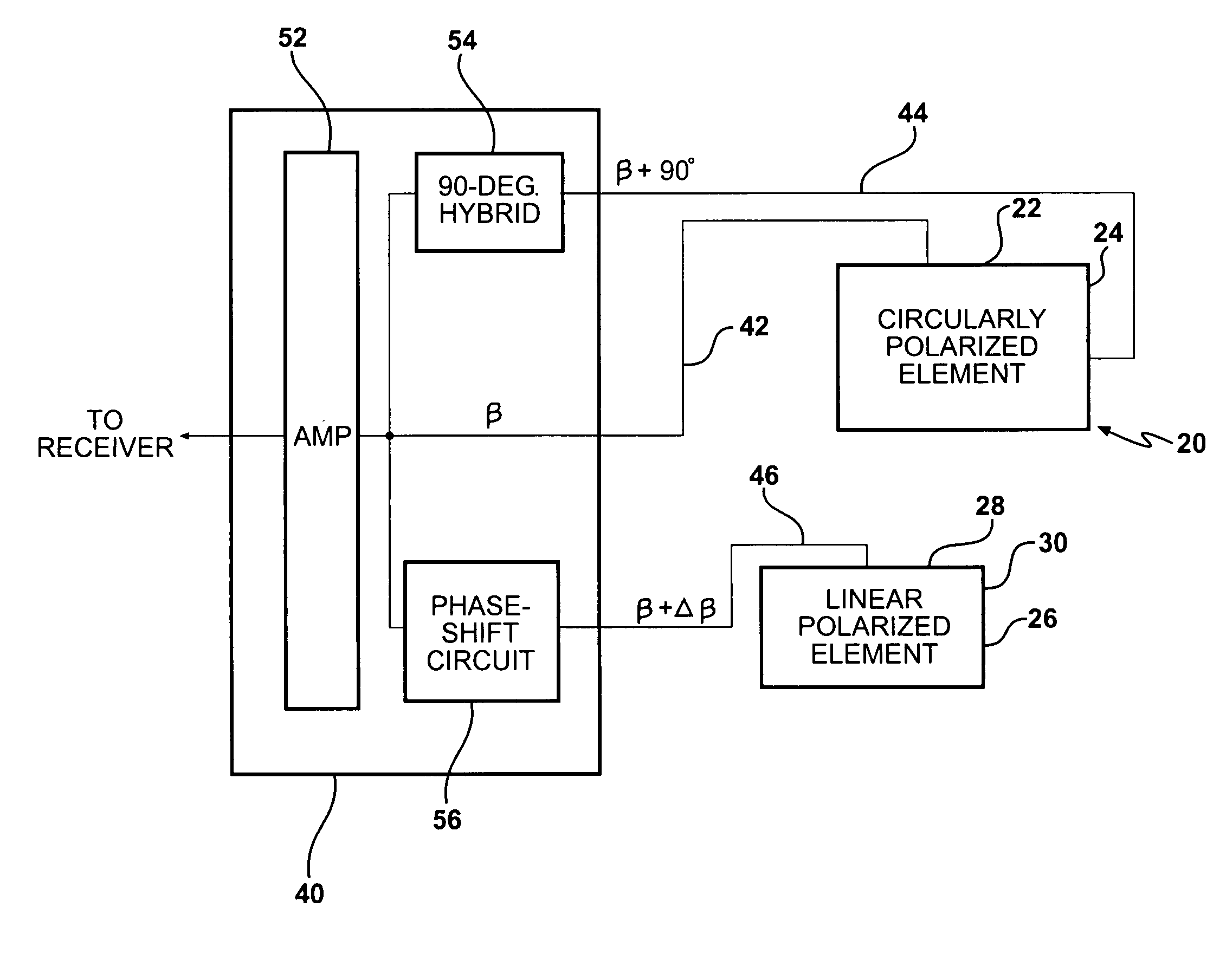
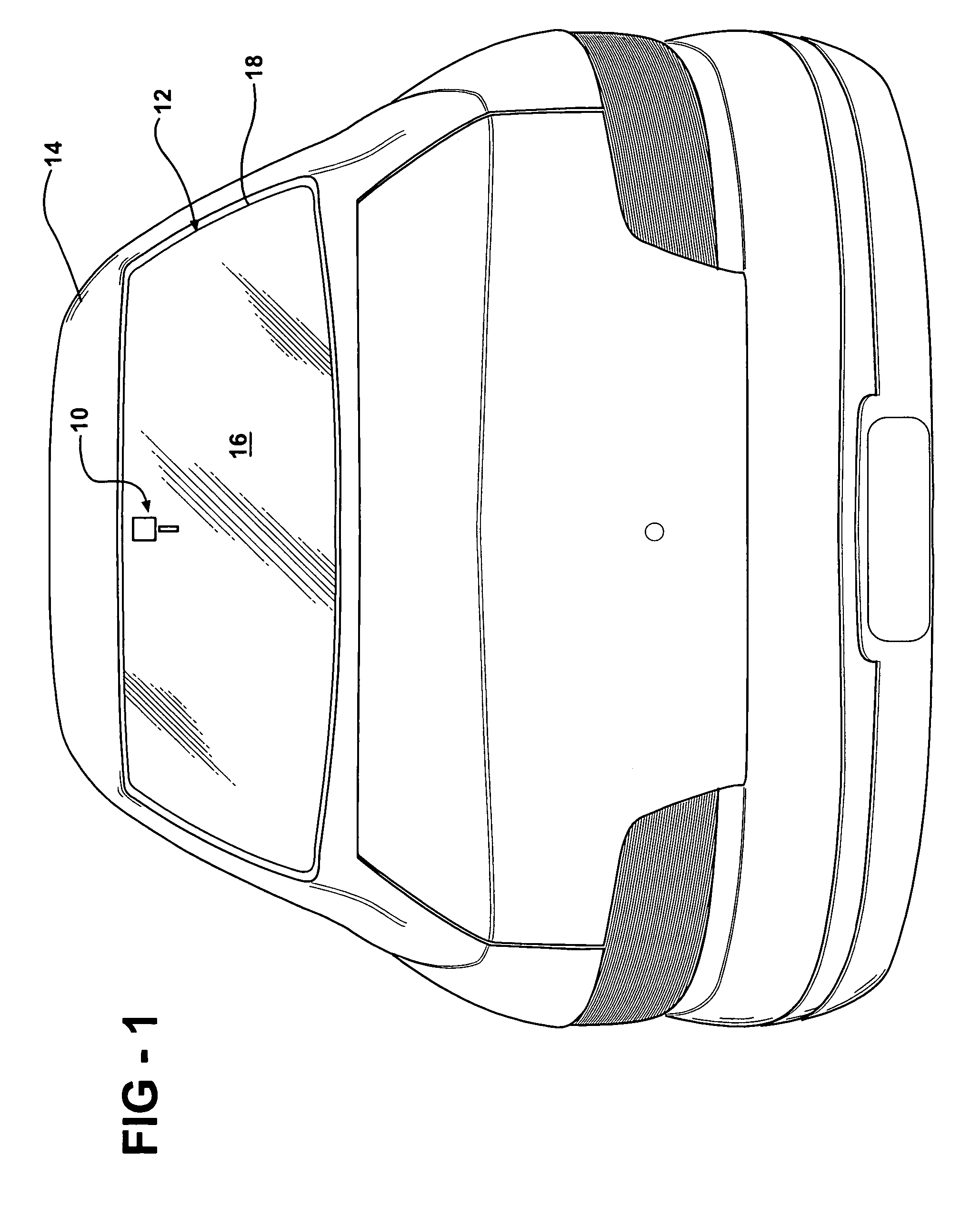
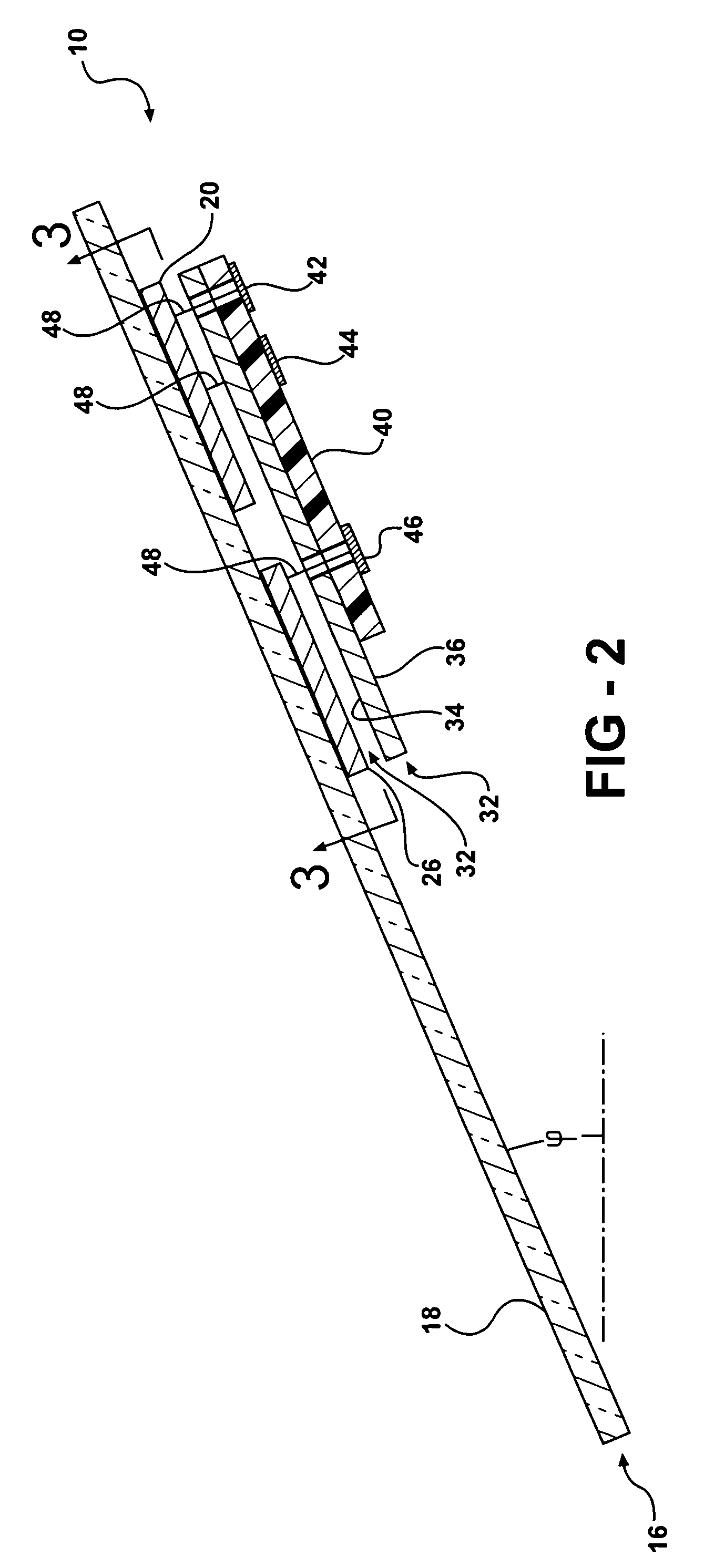
[0022]Referring to the Figures, wherein like numerals indicate like parts throughout the several views, an antenna is shown generally at 10. The antenna 10 is utilized to receive a circularly polarized radio frequency (RF) signal from a satellite and a linearly polarized RF signal from a terrestrial source. Specifically, the first embodiment of the antenna 10 receives a left-hand circularly polarized (LHCP) RF signal like those produced by a Satellite Digital Audio Radio Service (SDARS) provider, such as XM® Satellite Radio or SIRIUS® Satellite Radio, and their associated linearly polarized terrestrial repeater broadcasts. However, it is to be understood that the antenna 10 may also receive a right-hand circularly polarized (RHCP) RF signal. Also, the antenna 10 may also be configured to receive linearly polarized RF signals that are either vertically or horizontally orientated. XM® Satellite Radio produces a vertically orientated linearly polarized signal. Furthermore, those skille...


PUM


Abstract

An antenna for receiving and / or transmitting circularly and linearly polarized RF signals includes a circularly polarized radiation element and a linearly polarized radiation element. The radiation elements are disposed co-planar and spaced apart from each other on a pane of glass. The linearly polarized radiation element is fed with a phase-shifted signal line. A ground plane is disposed parallel to the radiation elements to sandwich a dielectric of air. The antenna produces the effect of tilting a radiation beam from a higher to a lower elevation angle to achieve a higher gain at lower elevation angles.

Description

BACKGROUND OF THE INVENTION[0001]1. Field of the Invention[0002]The subject invention relates to an antenna, specifically a multi-element antenna in an array-type configuration, for receiving a circularly polarized radio frequency (RF) signal from a satellite and a linearly polarized RF signal from a terrestrial source.[0003]2. Description of the Prior Art[0004]Vehicles have long implemented glass to enclose a cabin of the vehicle while still allowing visibility for the driver of the vehicle. Automotive glass is typically either a tempered (or toughened) glass or a laminated glass which is produced by bonding two or more panes of glass together with a plastic interlayer. The interlayer keeps the panes of glass together even when the glass is broken.[0005]Recently, antennas have been integrated with the glass of the vehicle. This integration helps improve the aerodynamic performance of the vehicle as well to help provide the vehicle with an aesthetically-pleasing, streamlined appeara...

Claims


Application Information

Patent Timeline
Patent Type & Authority Patents(United States)
IPC IPC(8): H01Q1/32
CPCH01Q1/1271H01Q21/24H01Q21/28H01Q1/32
Inventor KUBBA, SUNDUSVILLARROEL, WLADIMIRO
Owner AGC AUTOMOTIVE AMERICAS CO A DIV OF AGC FLAT GLASS NORTH AMERICA INC
Why Eureka
Try Eureka