Broadband circularly-polarized high-gain antenna

A high-gain antenna, circularly polarized technology, used in antennas, resonant antennas, electrical short antennas and other directions, can solve the problems of narrow antenna bandwidth-axis ratio bandwidth, antenna performance impact, complex feed structure and other problems, to achieve a simple and good structure. The effect of practicality

Inactive Publication Date: 2016-07-27
SOUTHEAST UNIV
View PDF3 Cites 11 Cited by
  • Summary
  • Abstract
  • Description
  • Claims
  • Application Information

AI Technical Summary

Problems solved by technology

Therefore, the problem is that the complex feed structure and the mutual coupling between elements affect th...

Method used


Image

  • Broadband circularly-polarized high-gain antenna
  • Broadband circularly-polarized high-gain antenna
  • Broadband circularly-polarized high-gain antenna

Examples


Embodiment Construction

[0024] The present invention will be further explained below in conjunction with the accompanying drawings and specific embodiments.

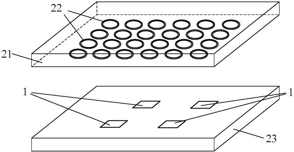
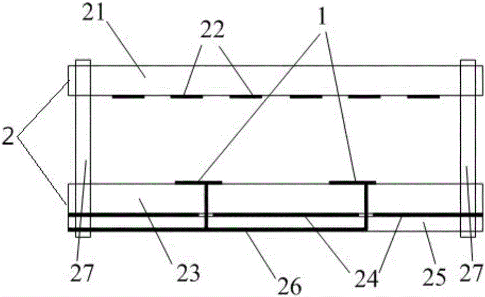
[0025] Such as Figure 1-3 As shown, the broadband circularly polarized high-gain antenna includes a resonant cavity 2, and the resonant cavity 2 includes an upper dielectric substrate 21 and a lower dielectric substrate 23 arranged in parallel to each other. The upper dielectric substrate 21 and the lower dielectric substrate 23 are spaced apart, and air can enter between them.

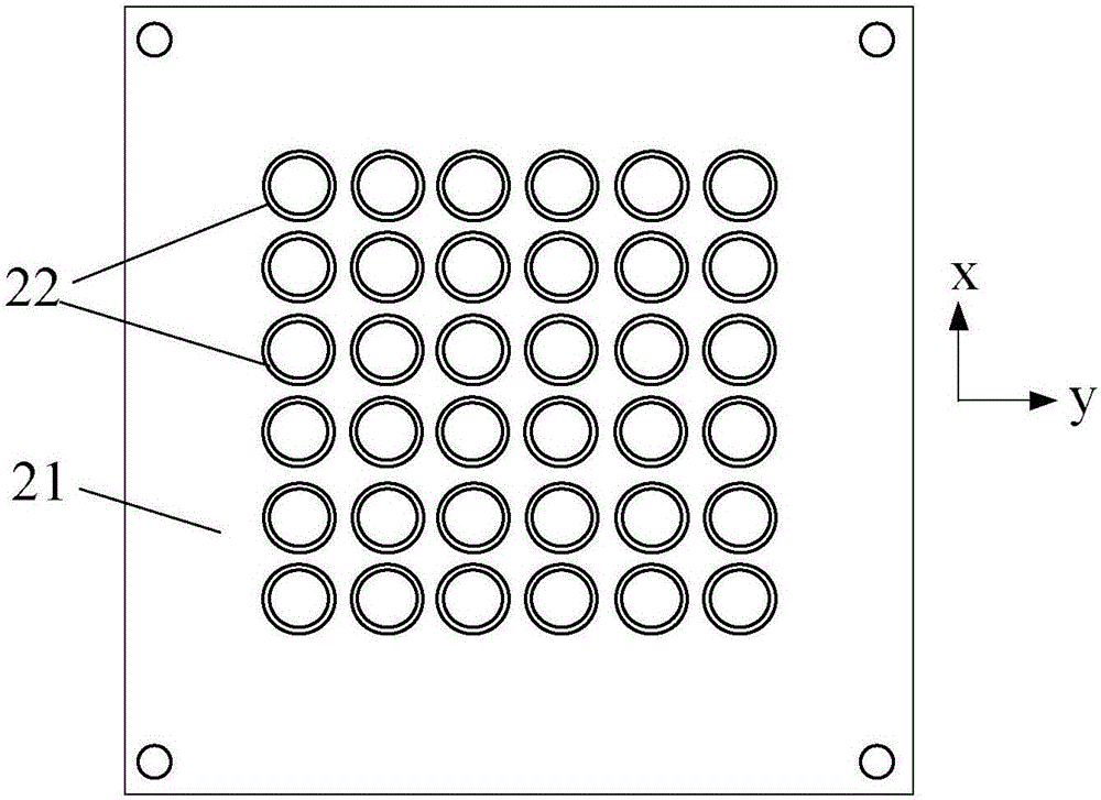
[0026] A part of the reflective surface is set on the lower surface of the upper dielectric substrate 21, and the part of the reflective surface is composed of several circular patches 22, which are periodically arranged along the orthogonal direction, and the circular patches 22 are directly printed on the on the lower surface of the upper dielectric substrate 21 . Of course, those skilled in the art have basic experimentation ability, and the partial reflective su...


PUM


Abstract

The invention discloses a wide-band circularly polarized high-gain antenna, which belongs to the technical field of circularly polarized antennas. Set a partial reflective surface; print the copper-clad surface on the lower surface of the lower dielectric substrate as a grounding plate, set a bottom plate under the grounding plate, print the feed network on the lower surface of the bottom plate, and print a circular pole on the lower dielectric substrate chemical radiation unit. The structure of the present invention is simpler, and the resonant cavity is formed by a part of the reflective surface and a ground plate parallel to the part of the reflective surface, and the gain of many array units can be significantly improved by using the resonance characteristics. At the same time, the structure between the circularly polarized radiation units Rotate 90 degrees in sequence to form broadband circular polarization; although the distance between the circularly polarized feed units of the present invention is much larger than the distance between conventional antenna array units, there is no grating lobe; it has good practicability.

Description

technical field [0001] The invention belongs to the technical field of circularly polarized antennas, in particular to a broadband circularly polarized high-gain antenna. Background technique [0002] Circularly polarized antennas play an important role in the radio field, especially in aerospace vehicles. Due to the fixed position and attitude of the aircraft, their communication measurement and control equipment requires circularly polarized antennas that are conformal, light in weight, small in size and low in cost. . Circularly polarized microstrip antenna is an ideal antenna that can meet these requirements. [0003] Modern radar, satellite communication and other fields usually require the use of circularly polarized antennas with higher gain. Antenna arrays are usually used to implement, and the number of array elements is large, so a complex feed network is required to achieve the amplitude and phase conditions of circular polarization. Therefore, the problem brou...

Claims


Application Information

Patent Timeline
IPC IPC(8): H01Q1/38H01Q1/28H01Q1/48H01Q9/04H01Q15/14
CPCH01Q1/38H01Q1/28H01Q1/48H01Q9/0428H01Q9/0464H01Q15/14
Inventor 刘震国陆卫兵
Owner SOUTHEAST UNIV
Why Eureka
Try Eureka