Wideband wide-beam circularly polarized dielectric resonator antenna fed by spiral slit

A dielectric resonator and wide beam technology, applied in the electronic field, can solve problems such as narrow bandwidth, increased design difficulty, complex feeding structure, etc., and achieve the effect of wide beam

Inactive Publication Date: 2016-01-20
UNIV OF ELECTRONICS SCI & TECH OF CHINA
View PDF1 Cites 11 Cited by
  • Summary
  • Abstract
  • Description
  • Claims
  • Application Information

AI Technical Summary

Problems solved by technology

The first method can achieve wider bandwidth, but it needs to introduce complex feed structure, which increases the difficulty of design
The second method has a simple feed structure, but the bandwidth is relatively narrow, generally only 3% of the 3dB axial ratio bandwidth

Method used


Image

  • Wideband wide-beam circularly polarized dielectric resonator antenna fed by spiral slit
  • Wideband wide-beam circularly polarized dielectric resonator antenna fed by spiral slit
  • Wideband wide-beam circularly polarized dielectric resonator antenna fed by spiral slit

Examples


Embodiment Construction

[0024] The specific implementation manners of the present invention will be further described in detail below in conjunction with the accompanying drawings.

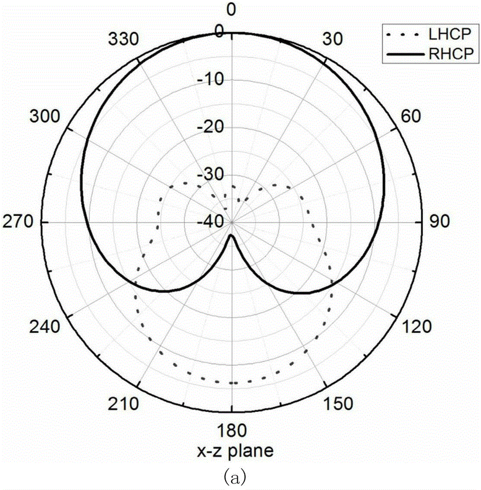
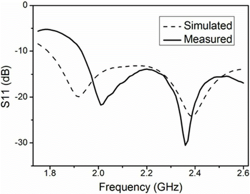
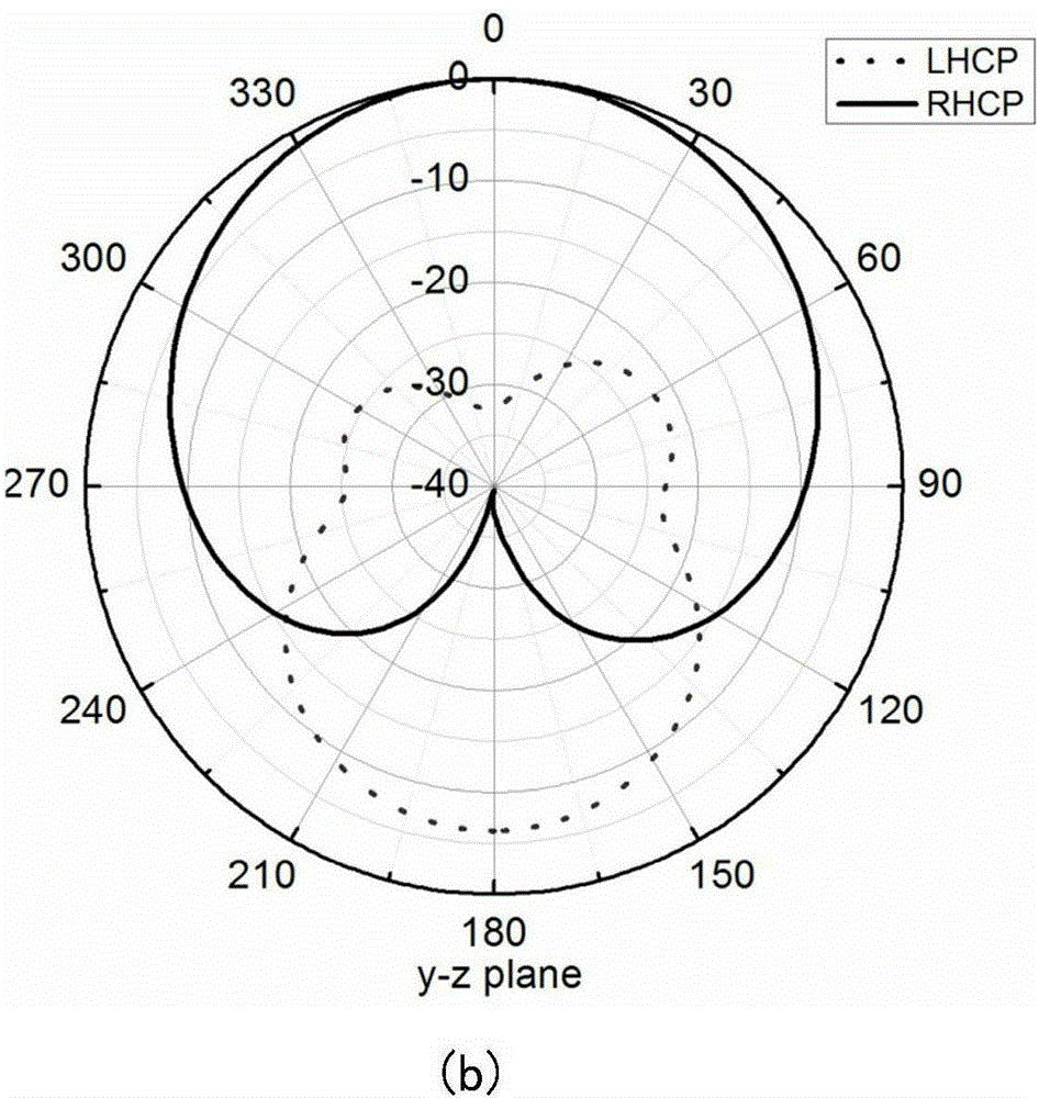
[0025] A schematic diagram of an embodiment of a wide-bandwidth wide-beam circularly polarized dielectric resonator antenna fed by a helical slot of the present invention is as follows figure 1 As shown in (a) and (b), it includes a rectangular dielectric substrate 1, a metal floor 6 that covers the front of the dielectric substrate and is etched with gaps, a chip resistor 4, a rectangular dielectric resonator 2, and a power supply for the antenna on the back of the substrate. Coaxial cable 7.

[0026] The relative dielectric constant of the dielectric substrate 1 is 2.2, the thickness is 2mm, and the cross-sectional size is 75*75mm 2 ; The rectangular dielectric resonator is a ceramic with a relative permittivity of 12, and its length a, width b, and height c correspond to the dimensions a=b=40mm, c=10cm; the Archimede...


PUM


Abstract

The invention relates to a wideband wide-beam circularly polarized dielectric resonator antenna fed by a spiral slit, and belongs to the technical field of electronics. The antenna comprises a rectangular dielectric substrate, a metal floor, a chip resistor, a rectangular dielectric resonator and a coaxial line, wherein the front surface of the dielectric substrate is covered by the metal floor; slits are etched in the metal floor; and the coaxial line is arranged on the back surface of the substrate for feeding the antenna. The wideband wide-beam circularly polarized dielectric resonator antenna is fed by the coaxial line; the energy is transmitted to the place below the slit through the coaxial line, and then the energy is coupled to the rectangular dielectric resonator through an Archimedes spiral slit to excite dominant modes which are shown as the formula in the specification; and circularly polarized radiation is generated by the two orthogonal modes. The wideband wide-beam circularly polarized dielectric resonator antenna realizes the wideband circularly polarized function through single point feed on the basis of the simple dielectric resonator structure, and the antenna is wider in beams.

Description

technical field [0001] The invention belongs to the field of electronic technology, and in particular relates to the technology of a wide-bandwidth wide-beam circularly polarized dielectric resonator antenna. Background technique [0002] The rapid development of modern wireless communication technology has inspired the research of circularly polarized dielectric resonator antenna (DRA) to solve the communication problem caused by polarization mismatch. At present, there are mainly two methods for realizing broadband circular polarization of dielectric resonator antennas: the first method is to use multi-point feeding, and the second method is to use single-point feeding. The first method can achieve a wider bandwidth, but it needs to introduce a complex feed structure, which increases the design difficulty. The second method has a simple feed structure, but its bandwidth is relatively narrow, generally only 3% of the 3dB axial ratio bandwidth. [0003] At present, some si...

Claims


Application Information

Patent Timeline
Patent Type & Authority Applications(China)
IPC IPC(8): H01Q1/36H01Q9/04
Inventor 潘锦邹孟吴凯崔元善张翔陈兆丰
Owner UNIV OF ELECTRONICS SCI & TECH OF CHINA
Why Eureka
Try Eureka