Wide beam multi-arm slot helical antenna

A technology of helical antenna and wide beam, applied in the field of wide-beam multi-arm slot helical antenna, can solve the problems of complex feeding structure of four-arm helical antenna, enhance the ability of coupling to metal slots, overcome the limitation of the number of arms, improve the The effect of antenna gain

Active Publication Date: 2017-09-26
XIDIAN UNIV
View PDF2 Cites 0 Cited by
  • Summary
  • Abstract
  • Description
  • Claims
  • Application Information

AI Technical Summary

Problems solved by technology

[0004] The object of the present invention is to overcome the shortcoming that above-mentioned four-arm helical antenna exists, has proposed a kind of wide-beam multi-arm slot helical antenna, is used to solve the problem that the feeding structure of existing four-arm helical antenna is complicated, to simplify the feeding structure of antenna, Improve the working performance of the antenna and expand its application range

Method used


Image

  • Wide beam multi-arm slot helical antenna
  • Wide beam multi-arm slot helical antenna
  • Wide beam multi-arm slot helical antenna

Examples


Embodiment 1

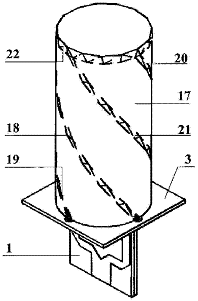
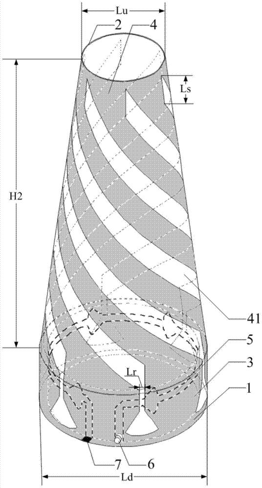
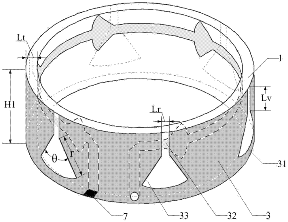
[0026] refer to figure 2 , the inner surface of the ring-shaped cylindrical dielectric substrate 1 is printed with a series fed microstrip line 5, and the outer surface of the ring-shaped cylindrical dielectric substrate 1 is printed with a ring-shaped cylindrical metal patch 3; 6 fan-shaped pieces are evenly distributed on the serial fed microstrip line 5 51; 6 uniformly distributed coupling adjustment slits 31 are etched on the annular columnar metal patch 3, the coupling adjustment slits 31 are composed of rectangular slits 32 and fan-shaped slits 33, and the radius and angle of each fan-shaped slit 33 are adjusted to ensure the The amplitude of the coupling feed is the same; the lower edge of the series-fed microstrip line 5 is on the same level as the lower edge of the rectangular slit 32, and the center of the fan-shaped piece 51 corresponds to the position of the rectangular slit 32, and its head end is connected to the inner core of the coaxial interface. The end is c...

Embodiment 2

[0029] The structure of embodiment 2 is identical with the structure of embodiment 1, and following parameter has been adjusted:

[0030] The outer diameter of the upper end of the annular tapered dielectric substrate 2 is Lu=0, and the number of radial spiral slots 41 , coupling adjustment slots 31 and sector pieces 51 is N=4.

Embodiment 3

[0031] The structure of embodiment 3 is identical with the structure of embodiment 1, and following parameter has been adjusted:

[0032] The outer diameter of the upper end of the annular tapered dielectric substrate 2 is Lu=40 mm, and the number of radial spiral slots 41 , coupling adjustment slots 31 and sector pieces 51 is N=8.

[0033] Effect of the present invention can be further explained in conjunction with simulation result:

[0034] 1. Simulation content

[0035] 1.1 Utilize commercial emulation software HFSS_15.0 to the S of above-mentioned embodiment 1 11 The parameters are simulated and calculated, and the results are as follows Figure 5 shown.

[0036] 1.2 Utilize the commercial simulation software HFSS_15.0 to simulate the axial ratio of the above-mentioned embodiment 1, the results are as follows Figure 6 shown.

[0037] 1.3 Utilize the commercial simulation software HFSS_15.0 to simulate and calculate the far-field radiation pattern of the above-mentio...


PUM


Abstract

The invention discloses a wide-beam multi-arm slot helical antenna, which is used to solve the problem of complex feed structure of the existing four-arm helical antenna. Including annular cylindrical dielectric substrate (1), annular conical dielectric substrate (2), annular cylindrical metal patch (3), annular conical metal patch (4), series-fed microstrip line (5), coaxial interface ( 6) and load resistor (7); the inner and outer surfaces of the annular columnar dielectric substrate (1) are respectively printed with a series-fed microstrip line (5) and an annular columnar metal patch (3). The series-fed microstrip line (5) N evenly distributed sector-shaped pieces (51) are provided on the annular columnar metal patch (3), and coupling adjustment gaps (31) corresponding to the sector-shaped pieces (51) are etched on the annular columnar metal patch (3); the outer surface of the annular cone-shaped dielectric substrate (2) An annular conical metal patch (4) printed with etched radiating spiral slits (41). The invention has the advantages of simple feed structure and wide beam, and can be used in fields such as communication and navigation.

Description

technical field [0001] The invention belongs to the technical field of antennas, and relates to a wide-beam multi-arm slot helical antenna, which can be used for communication, navigation and other multifunctional aircraft integrated system antennas. Background technique [0002] The key role of the global satellite navigation and positioning system GNSS is to provide time, space reference and all real-time dynamic information related to the position. It is a strategic deterrent basic resource and a major technical support system for national defense security, homeland security, public security and economic security. At present, the satellite navigation systems in operation around the world include the GPS system of the United States, the GLONASS system of Russia, the Galileo system of Europe and the Beidou second-generation satellite navigation and positioning system of China. Due to the instability of the phase center of the general antenna, it will cause errors of centim...

Claims


Application Information

Patent Timeline
Patent Type & Authority Patents(China)
IPC IPC(8): H01Q1/50H01Q1/38H01Q13/12
Inventor 郭景丽杨宇航邹艳林邓敬亚孙保华
Owner XIDIAN UNIV
Why Eureka
Try Eureka