
Method and apparatus for packet-based media communication

Active Publication Date: 2006-02-28
APPLE INC
View PDF26 Cites 61 Cited by
  • Summary
  • Abstract
  • Description
  • Claims
  • Application Information

AI Technical Summary

Benefits of technology

[0020]An advantage of the present invention is that it allows a first encoding type common to all media signal sources in a given conference and a second encoding type common to a subset of the media signal sources in the given conference to be established. Typically, the first encoding type will be a basic, and hence less complex, encoding type and the second encoding type will be an enhanced encoding type, and hence of a higher complexity than the first encoding type. All the media signal sources in the conference communicate with one another using the first encoding type and the subset of media signal sources communicate using the second encoding type.

Problems solved by technology

A deficiency in systems of the type described above is, in the case where the encoding is a compression-type encoding, the degradation in the quality of the media information as the media information is encoded and decoded multiple times during the propagation of the media data packets.
Another deficiency is that the encoding and decoding operations at the conference bridge require significant computing capabilities.
A deficiency with current conference systems designed to reduce the occurrence of back-to-back (tandem) encode-decode operations is that they do not provide any suitable functionality for supporting multiple encoding types within a given conference.
Therefore, unless all media signal sources in the conference implement the enhanced encoding functionality, the enhanced encoding functionality provided by the media signal source is essentially rendered nearly useless by current conferencing systems.

Method used


Image

  • Method and apparatus for packet-based media communication
  • Method and apparatus for packet-based media communication
  • Method and apparatus for packet-based media communication

Examples


Embodiment Construction

Conferencing System

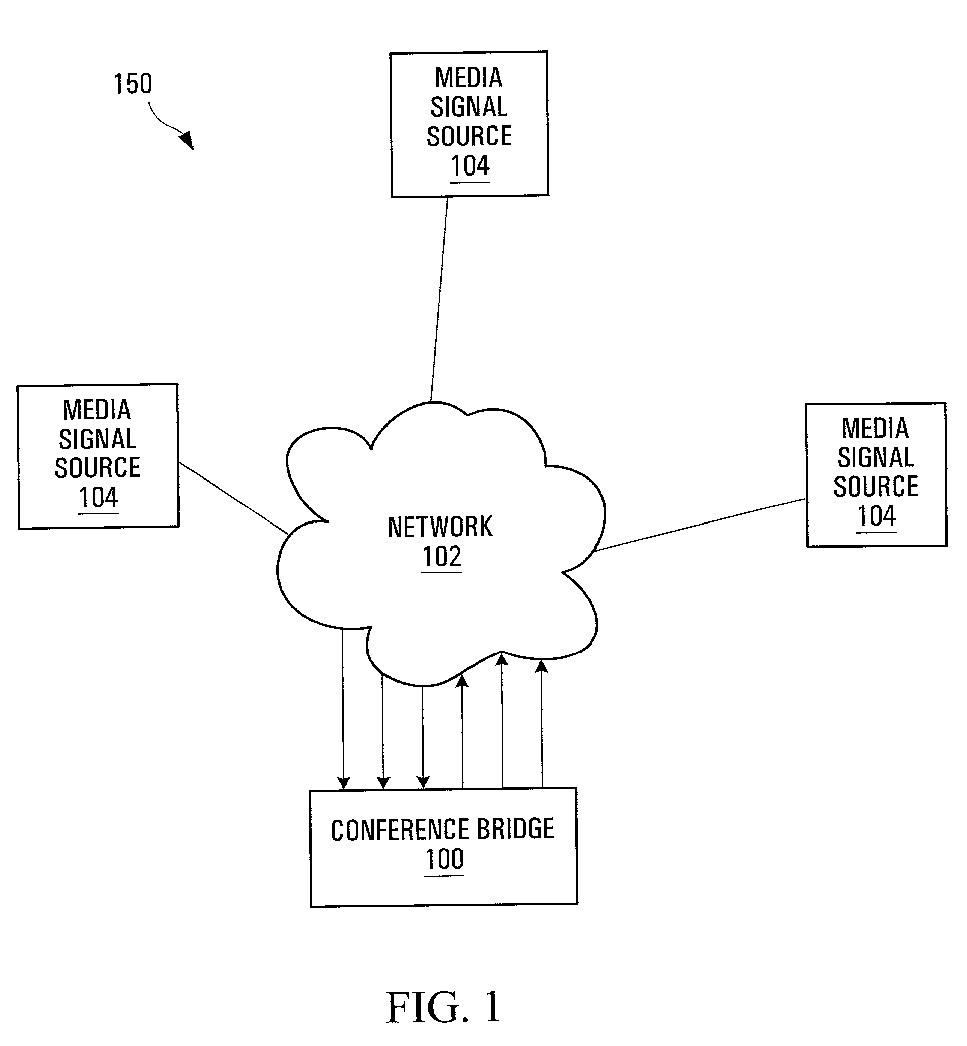
[0062]FIG. 1 of the drawings depicts a media conferencing system 150 providing media conferencing functionality. The media conferencing system 150 includes a plurality of media signal sources 104 connected to conference bridge 100 through network 102. Network 102 is a packet switched network that suitably carries packets between media signal sources 104 and conference bridge 100. The specific configuration of the networks 102 is not critical to the invention and any suitable network can be used to provide connectivity between the plurality of media signal sources 104 and the conference bridge 100. Such packet based networks are well known and, as such, need not be described further here. In operation, the media signal sources 104 exchange with the conference bridge 100 media packets including conference management activities and / or encoded media information through network 102. The conference bridge 100 accepts and releases media packets and processes them if nece...


PUM


Abstract

A conference bridge is provided for managing a conference between media signal sources generating media data packets conveying encoded media information and encoding type information. The media signal sources, in order to enter a conference, generate link messages including respective supported encoding types and transmit the link messages to the conference bridge. The conference bridge receives the link messages and processes them to derive a first common encoding type supported all media signal sources in the conference and a second encoding type supported a subset of media signal sources in the conference. The conference bridge generates link message reply signals conveying the first encoding type and the second encoding type the subset of media signal sources and conveying at least the first encoding type to the media signal sources other than the subset of all media signal sources. Each media signal source is responsive to the link message reply signal to render active at least the first encoding type and selectively render active the second encoding type.

Description

[0001]This application claims benefit of U.S. Provisonal Application 60 / 266,404 filed Feb. 2, 2001.FIELD OF THE INVENTION[0002]This invention relates generally to a packet-based media communication system and more specifically to media conferencing within a packet-based communication network.BACKGROUND OF THE INVENTION[0003]It is known to effect media conferencing by using a conference bridge. A conference bridge is a device that facilitates conferencing between multiple conference participants operating respective terminal units. In a typical interaction, the conference bridge receives a plurality of media signals from multiple conference participants and selects the participants that are determined to have the most active speech signal for transmission to the other participants of the conference.[0004]In a packet-based communication system, the media signals are in the form of packets. The packets generally include encoded media information and header information. Typically, in su...

Claims


Application Information

Patent Timeline
IPC IPC(8): H04L12/16H04M3/42H04L29/06H04W88/18
CPCH04L29/06H04L29/06027H04W88/181H04L65/103H04L65/104H04L65/607H04L65/4038H04L65/605H04L65/765H04L65/70H04L9/40H04L65/1101
Inventor RABIPOUR, RAFICOVERDALE, PAULSMITH, PAXTON
Owner APPLE INC
Learn More