Latch needle for a loop-forming textile machine

a technology of textile machine and latch, which is applied in the field of latch needle for loop-forming textile machine, can solve the problems of narrow limits set to the elastic spreading open of the latch cheek, the concept has not been successful in practice, and the latch can be broken, so as to reduce reduce the moment of inertia , the effect of reducing the total weight of the latch

Active Publication Date: 2006-03-07
GROZ BECKERT KG
View PDF13 Cites 4 Cited by
  • Summary
  • Abstract
  • Description
  • Claims
  • Application Information

AI Technical Summary

Benefits of technology

[0009]The above object generally is achieved by the latch needle of the invention for a loop-forming textile machine, in particular a knitting machine, which generally includes a needle body with a hook disposed on one end of the needle body and a bearing device disposed on the needle body in the vicinity of the hook. At least one or even a plurality of indentations, are provided on the opposite end of the latch remote from the bearing device in addition to the shaped face that is present anyway. The shaped face is for instance a spoonlike depression for receiving the hook tip (grooved-latch needle). The shaped face may also be a riblike or slightly arching protrusion that engages a recess of the hook (grooved-hook needle). In both cases, the at least one indentation according to the invention is located on the free end of the latch, that is, approximately in the region that comes into contact with the hook. The indentation reduces the total weight of a latch slightly. Because of the great distance of the indentation from the pivot axis, this reduction has a disproportionate influence on the moment of inertia of the latch. Even a slight weight reduction thus causes a considerable reduction in the moment of inertia. In experiments, depending on the embodiment of the indentation, it was possible to reduce the moment of inertia by between 5% and 10% compared to commercially available needles without an indentation. As a result, wear to the hook tip, to the shaped face of the latch, and possibly also to the latch bearing can also be reduced. Tests have shown that the risk that the knitting tool will be destroyed, for instance by breakage of cheeks, latch holes, latch heads, and latch noucats, is reduced. Thus the latch needles of the invention when used in the conventional way have an increased service life. On the other hand, they also make it possible to increase the operating speed (machine rpm). The indentations are disposed for instance on a side of the latch remote from the hook. They differ in this respect from the shaped face oriented toward the hook, which may be embodied as a depression or as a protrusion. The indentations are preferably embodied as relatively shallow depressions, whose flanks preferably extend away from one another at an obtuse angle. The tendency of accumulations of deposits in these depressions is thus averted.
[0010]Preferably, two recesses are provided on the side and back faces of the latch. If the depressions are disposed on the oblique side faces of the latch that are remote from the hook, approximately at the level of the center of surface area of the cross section of the latch head, then high rigidity of the latch is furthermore achieved.
[0011]Instead of the depressions, the indentations may also be embodied as openings or may include openings. This can be utilized for a further reduction in the moment of inertia of the latch without substantially impairing its strength or rigidity. Moreover, such openings or other kinds of recesses have hardly any harmful influence on the strength of the latch, when they are disposed in the end region of the latch. The end region is considered to the portion of the latch that cooperates with the hook and comes into contact with it.

Problems solved by technology

Because of the high accelerations that the latch needles and hence the latches are exposed to, breaks of the latch shank can occur.
However, this concept has not been successful in practice.
However, narrow limits are set to the elastic spreading open of the needle shank cheeks.
However, in these mending needles, which cannot be compared with normal needle latches, the needle latch itself is bulky, and a spoon is dispensed with.
However, these recesses lead to a considerable weakening of the shank, which can cause latch shank breakages.

Method used


Image

  • Latch needle for a loop-forming textile machine
  • Latch needle for a loop-forming textile machine
  • Latch needle for a loop-forming textile machine

Examples


Embodiment Construction

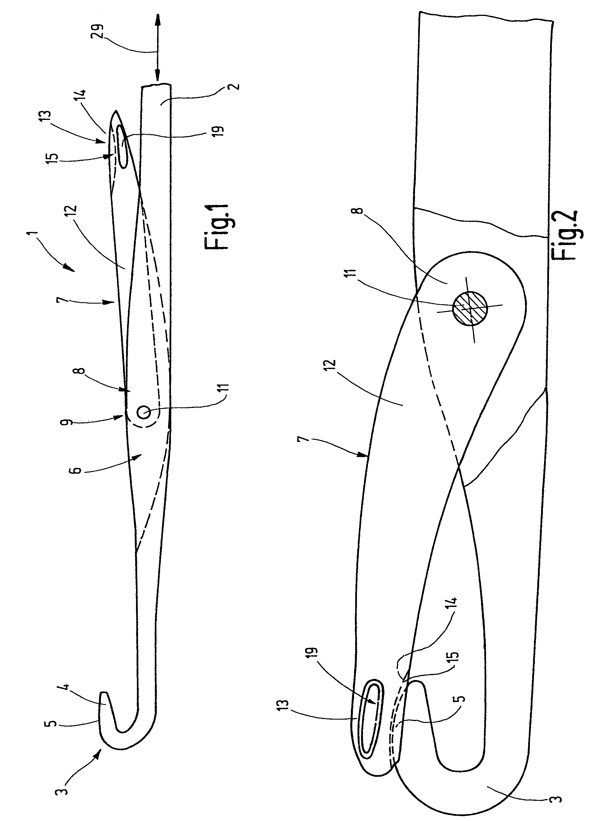
[0022]In FIG. 1, a latch needle 1 is shown, which has a needle body 2 with a hook embodied on its end. The hook 3 is provided with a tip 4, which may be rounded on its top side 5.

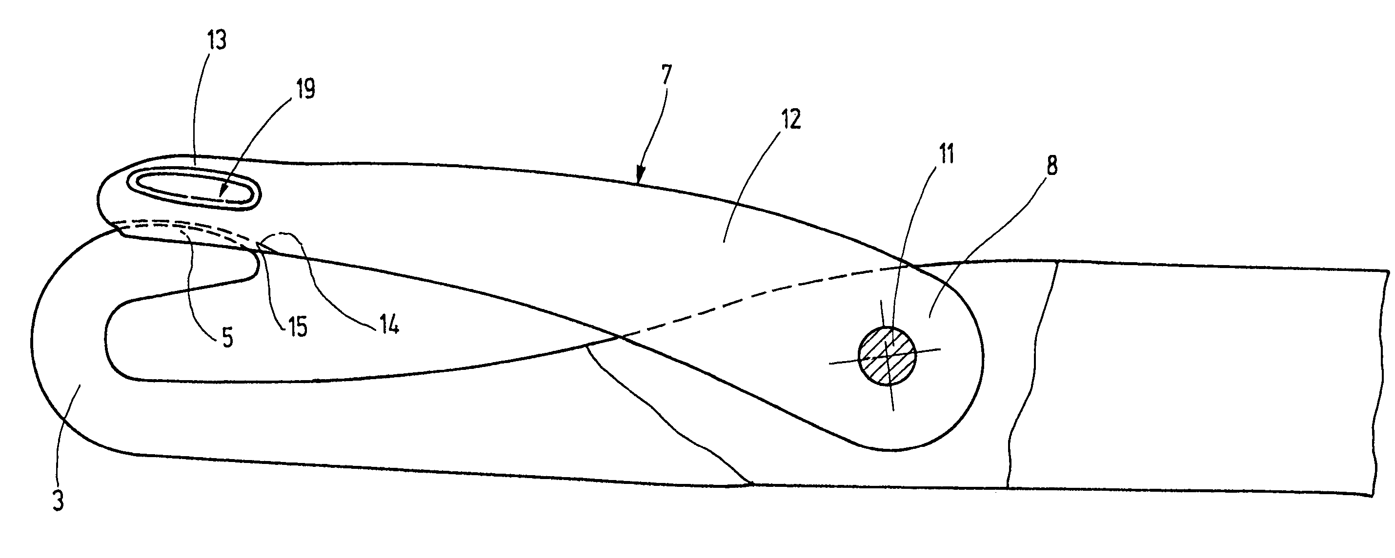
[0023]Not far away from the hook 3 in the needle body 2, a latch slot 6 is provided, into which a latch protrudes by one end 8. The latch is held and pivotably supported in the latch slot 6 on a bearing device 9. The bearing device 9 is preferably formed for example by a one-piece or multi-piece pin 11 passing transversely through the latch slot 6. The latch 7 can be pivoted about this pin 11 out of the standing position shown in FIG. 1 into the closing position shown in FIG. 2.

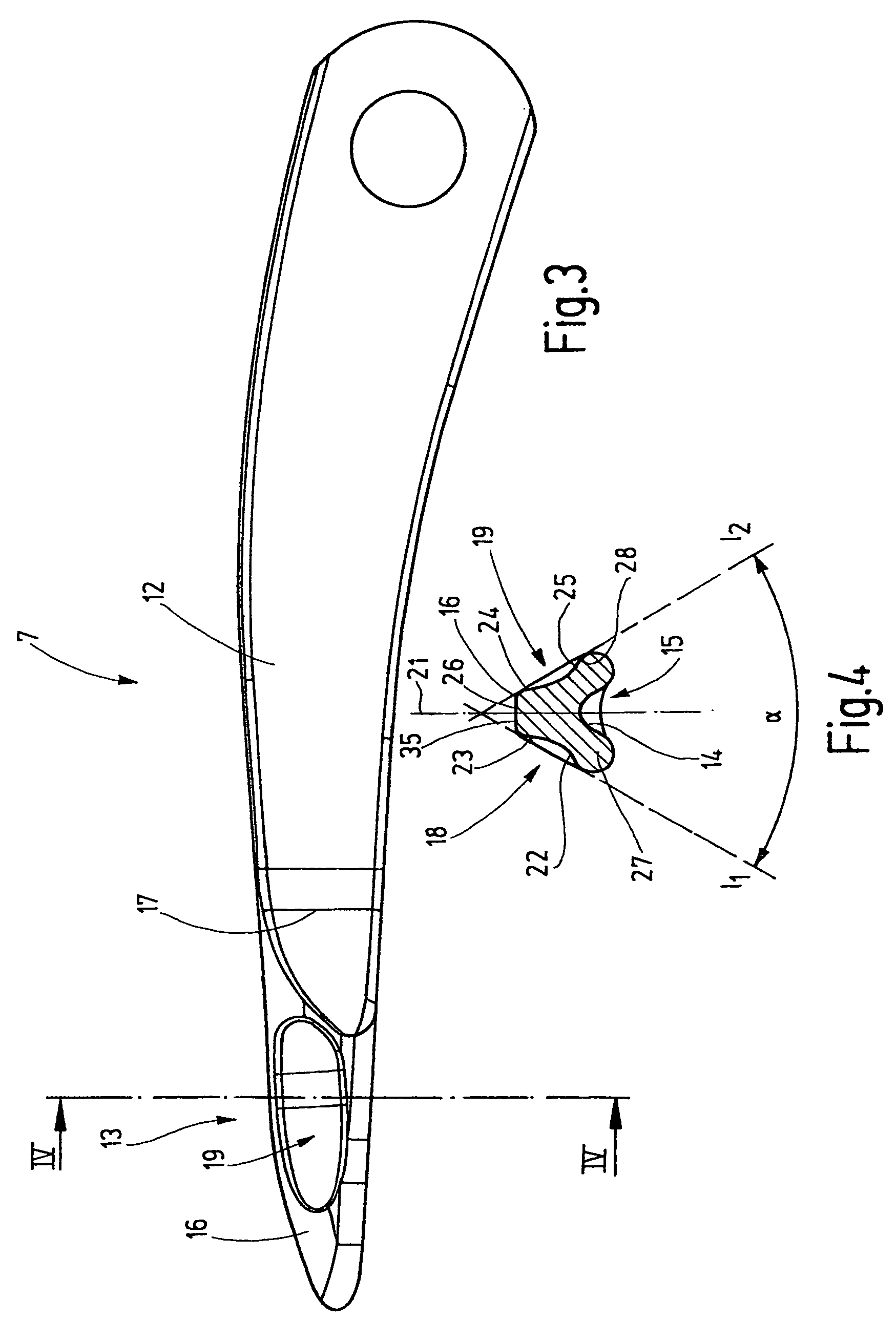
[0024]The latch has a narrow shank 12, which is preferably defined by parallel flanks and whose width is slightly less than that of the latch slot 6. The length of the latch 7 is dimensioned such that with its end 13 it can reach the top side 5 of the hook 3. The end 13, on the side toward the hook 3, is provided with a shaped face 1...


PUM


Abstract

The latch needle (1) of the invention has a latch (7), which is provided on its free end, on its side facing away from the hook (3), with one or more recesses (18, 19). The function of these recesses is to reduce the moment of inertia of the latch (7), which leads to an increased service life of the latch. Between the recesses (18, 19), a rib remains, whose top side functions like a skid for loops to be transferred. The indentations (18, 19) are preferably elongated depressions. However, corresponding openings may be provided as a substitute instead.

Description

CROSS REFERENCE TO RELATED APPLICATION[0001]This application claims the priority of European Patent Application No. 04 008 294.3, filed on Apr. 6, 2004, the subject matter of which, in its entirety, is incorporated herein by reference.FIELD OF THE INVENTION[0002]The invention relates to a latch needle for a loop-forming textile machine, in particular for a knitting machine.BACKGROUND OF THE INVENTION[0003]In knitting machines or in other loop-forming machines, so-called latch needles are often employed, which for forming loops are moved back and forth in rapid succession. The latches, which are provided on the needles and pivotably supported, open and close in rapid succession. In the process, they strike the hook of the latch needle and its shank in alternation. Because of the high accelerations that the latch needles and hence the latches are exposed to, breaks of the latch shank can occur. In the past, the attempt was made by various procedures to reduce the number of latch shank...

Claims


Application Information

Patent Timeline
Patent Type & Authority Patents(United States)
IPC IPC(8): D04B35/04
CPCD04B35/04A01C1/044
Inventor SAUTER, MANFRED
Owner GROZ BECKERT KG
Why Eureka
Try Eureka