Configured and sized cannula

a cannula and a technology of cannulas, applied in the field of wide-channel cannulas, can solve the problems of obstruction of surgeon's vision, pain and discomfort, and additional bleeding

Inactive Publication Date: 2006-03-07
DEPUY SYNTHES PROD INC
View PDF142 Cites 294 Cited by
  • Summary
  • Abstract
  • Description
  • Claims
  • Application Information

AI Technical Summary

Problems solved by technology

Obviously, this surgery is a source of pain and discomfort for the patient and creates an additional surgical step for the surgeon.
Moreover, this additional surgery causes additional bleeding and as a consequence, creates an obstruction to the vision of the surgeon.
Obviously, a cylindrical device as has been heretofore available and as disclosed in U.S. Pat. No. 6,159,179 supra, which is equidistant from the axis, does not allow for this approach.
Obviously, the human spine's skeletal structure, i.e. lateral facets and medial spinous process, restricts the amount of lateral space available.
In a cylindrical cannula, since a limitation of the lateral space that is available to locate a retractor, the vertical space is likewise limited.
As a consequence, the cylindrical cannula limits the number of patients who are candidates for minimally invasive spinal surgery necessitating the more invasive type surgery with all of the problems associated therewith.
Hence, for a large segment of the patient population, the only surgery available is the more destructive invasive muscle burning and stripping approach.
A 16 mm cylindrical retractor would fit tightly against the lamina but even with “wanding” (moving up and down) it would restrict the surgeons ability to reach much more than the 16 mm in vertical access.

Method used


Image

  • Configured and sized cannula
  • Configured and sized cannula
  • Configured and sized cannula

Examples


Embodiment Construction

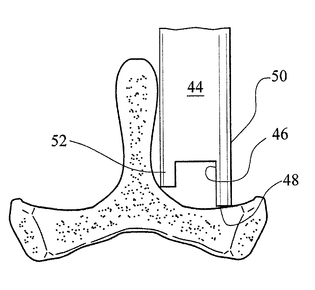
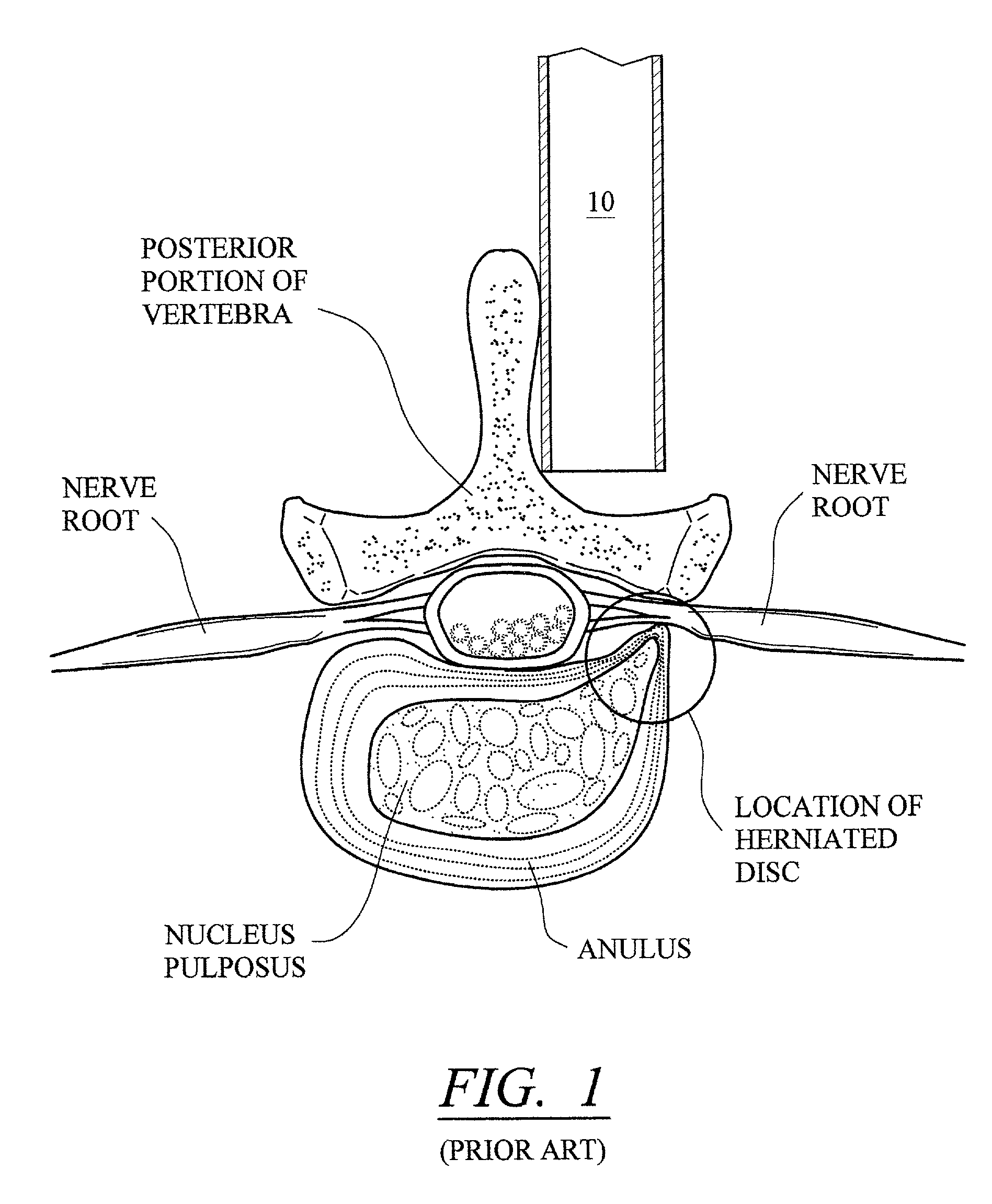
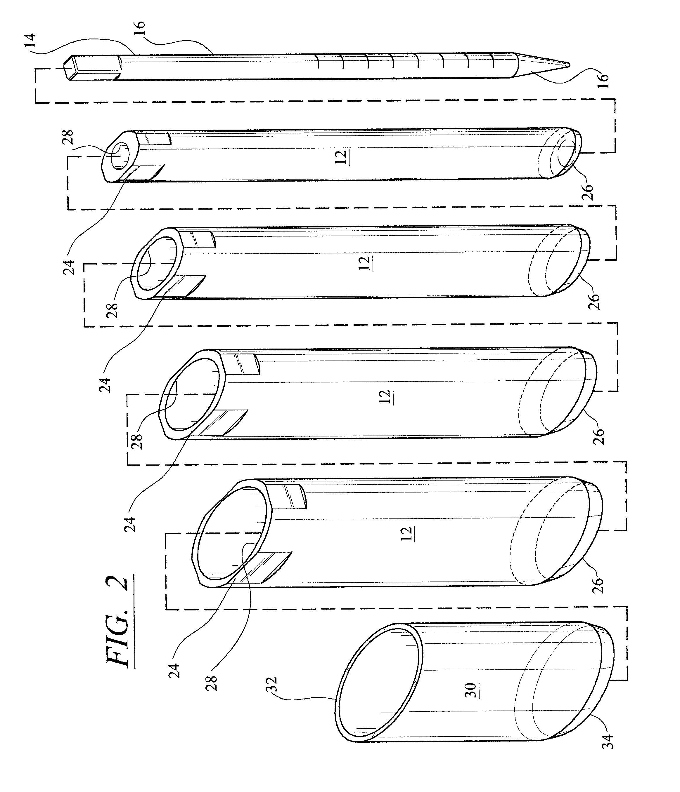
[0030]While the preferred embodiment of this invention is described herein, it will be appreciated, as one skilled in this art will recognize, that the invention although directed toward non-cylindrically shaped dilator retractors, under certain circumstances, the invention contemplates cylindrically shaped dilator retractors where the bottom or distal end is configured to accommodate the shape of the bone structure of the patient or to accommodate different procedures that are available to the surgeon. As for example, the distal end of a cylindrically shaped dilator retractor may be tunneled so as to allow the insertion of an implant. The terms “cannula” and “dilator retractor” have the same meaning and are used herein interchangeably. The term cavity as used herein means the cavity that is created by the dilators and when the dilator retractor is inserted in this cavity it becomes a working channel for the surgeons use in performing the minimal invasive surgery. While the inventio...


PUM


Abstract

A dilator retractor and the dilators that are used for minimally invasive spinal surgery or other surgery are configured to accommodate the anatomical structure of the patient as by configuring the cross sectional area in an elliptical shape, or by forming a funnel configuration with the wider end at the proximate end. In some embodiments the distal end is contoured to also accommodate the anatomical structure of the patient so that a cylindrically shaped, funnel shaped, ovoid shaped dilator retractor can be sloped or tunneled to accommodate the bone structure of the patient or provide access for implants. The dilator retractor is made with different lengths to accommodate the depth of the cavity formed by the dilators.

Description

CROSS REFERENCE[0001]This invention relates to the material disclosed and claimed in a co-pending patent application by the same inventor entitled “Non Cannulated Dilators” and bearing Ser. No. 10 / 021,809 and incorporated herein by reference.TECHNICAL FIELD[0002]This invention relates to medical instruments for use in surgical procedures and more particularly to a wide-channel cannula that is pre-sized, pre-configured and tailored to conform to the patient's anatomy.BACKGROUND OF THE INVENTION[0003]In one aspect of this invention, the invention considers the anatomical shape of the area of the patient being operated on and tailors the shape of the dilators and the dilator retractor or cannula to accommodate that shape. In another aspect of this invention, the invention constitutes an improvement over the apparatus and method disclosed and claimed in U.S. Pat. No. 6,159,179 granted on Dec. 12, 2000 to the inventor of this patent application and entitled “Cannula and Sizing and Insert...

Claims


Application Information

Patent Timeline
Patent Type & Authority Patents(United States)
IPC IPC(8): A61F5/00A61B17/58A61B17/00A61B17/02A61M29/00
CPCA61B17/0218A61B17/025A61B17/86A61M29/02A61B1/32A61B17/7002A61B17/3417A61B17/3421A61B2017/3443A61B2017/0256A61B2017/3433A61B17/56A61B2017/564
Inventor SIMONSON, ROBERT E.
Owner DEPUY SYNTHES PROD INC
Why Eureka
Try Eureka