
Radio frequency antenna for a tire and method for same

a technology of radio frequency antenna and tire, which is applied in the direction of instruments, protective material radiating elements, burglar alarm mechanical actuation, etc., can solve the problems of increasing the dissipation problem, affecting the transmission range, so as to improve the transmission range and improve the antenna processing and tuning. , the effect of high frequency transmission

Inactive Publication Date: 2006-03-07
MICHELIN RECH & TECH SA
View PDF19 Cites 46 Cited by
  • Summary
  • Abstract
  • Description
  • Claims
  • Application Information

AI Technical Summary

Benefits of technology

[0007]The present invention provides a radio frequency antenna for embedding within a conductive dielectric material (such as tire rubber), and a method of embedding a radio frequency antenna in a conductive, dielectric material. The present invention is particularly effective for very high frequency transmission and results in improved communication ranges. Improvements in both antenna processing and tuning are also provided by the present invention.

Problems solved by technology

An antenna in direct contact or embedded in the tire, however, presents difficulties.
In addition, conductive dielectric material in contact with an antenna allows radio frequency current to pass between the two adjacent feed points of the antenna, also dissipating radio frequency energy.
The problem of dissipation increases with the frequency, and is particularly troublesome at or above very high frequency (130 MHz) operation.
Furthermore, placement of the antenna within a dielectric material such as tire rubber causes significant changes in the resonance and impedance of the antenna, making the antenna appear longer from an electrical standpoint than when in free air.
Finally, physical problems are also encountered when embedding or otherwise placing an antenna in direct contact with a tire.

Method used


Image

  • Radio frequency antenna for a tire and method for same
  • Radio frequency antenna for a tire and method for same
  • Radio frequency antenna for a tire and method for same

Examples


Embodiment Construction

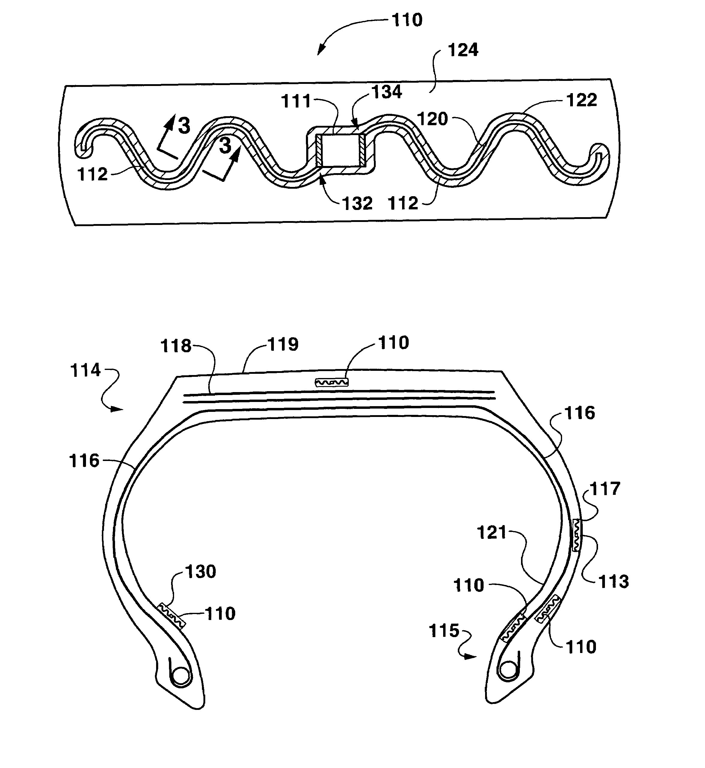
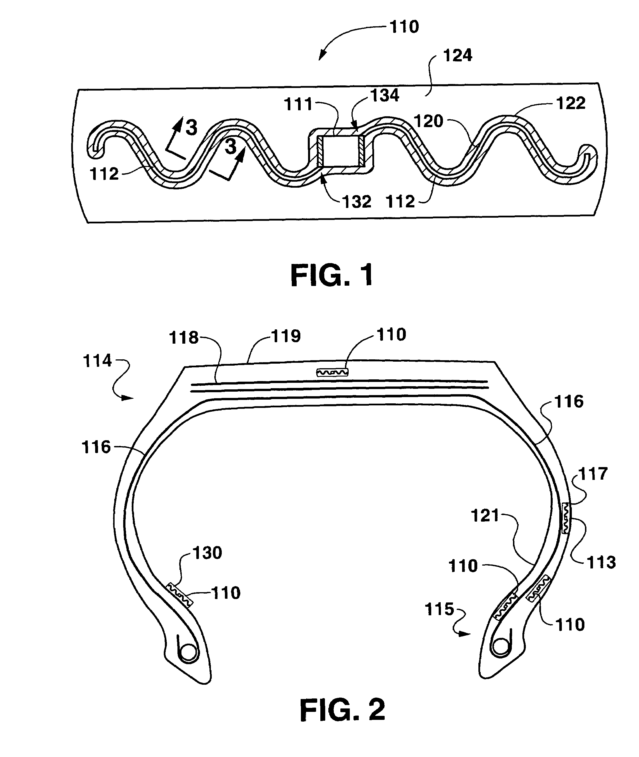
[0015]Illustrated in FIG. 1 is an exemplary embodiment of an insulated radio frequency device 110 in a tire 114 (FIG. 2) according to the present invention. Device 110 includes a radio component 111 and an antenna 112. Device 110 may be an identification or tracking device, such as may be used in manufacturing, distribution, and sales activities. Device 110 may also be or include a monitoring device for measuring temperature, pressure or other physical parameters in tire 114 during operation. For example, antenna 112 in device 110 may be used to transmit, receive, and / or reflect information to or from an external device by radio frequency. As another example, antenna 112 may also serve to receive energy from an interrogation device external to tire 114. Such radio devices 110 may operate as receivers, transmitters, transponders or reflectors, and, because the antenna of the invention is useful for all these devices, in the following description, the term “radio frequency device” is ...


PUM

PropertyMeasurementUnit
Thicknessaaaaaaaaaa
Electrical resistanceaaaaaaaaaa

Abstract

A radio frequency antenna for embedding within a conductive, dielectric material (such as tire rubber) is provided along with a method of embedding a radio frequency antenna in such a material. For very high frequency transmission, improved communication ranges are provided along with improvements in both antenna processing and tuning.

Description

PRIORITY CLAIM[0001]This application is a continuation-in-part of application of U.S. application Ser. No. 10 / 775,623, pending, filed Feb. 10, 2004, which is a continuation of PCT / US02 / 38411, filed Dec. 3, 2002 (designating the U.S.), which is a continuation-in-part of PCT / US02 / 18411, filed Jun. 11, 2002 (designating the U.S.), for which the benefits thereof are hereby claimed.TECHNICAL FIELD OF THE INVENTION[0002]The present invention provides a radio frequency antenna for embedding within a conductive, dielectric material (such as tire rubber), and a method of embedding a radio frequency antenna in a conductive, dielectric material.BACKGROUND OF THE INVENTION[0003]Electronic devices integrated with a tire can provide functions such as identification and tracking during manufacture, distribution, and use. These electronics can also provide for measurement of physical parameters such as pressure and temperature during use of the tire. Many systems utilize radio frequency communicati...

Claims


Application Information

Patent Timeline
IPC IPC(8): H01Q1/40B60R11/02B60C11/00B60C13/00B60C19/00B60C23/04G06K19/077H01Q1/22H01Q1/32H01Q9/16H01Q9/26H01Q9/28
CPCB60C11/00B60C13/00B60C19/00B60C23/0433B60C23/0493H01Q9/28G06K19/07764H01Q1/22H01Q1/2241H01Q1/32H01Q9/16H01Q9/26G06K19/07749B29D2030/0077
Inventor ADAMSON, JOHN DAVIDKELLY, CHARLES EDWARDSMITH, CAMERON EARLMORELAND, CAL
Owner MICHELIN RECH & TECH SA
Learn More