
Systems and methods for controlling an image forming system based on customer replaceable unit status

a technology customer replacement, applied in the field of image forming system, can solve the problems of reducing the productivity and additional cost of users and/or customers, affecting the quality of image production, so as to avoid the delay of document printing due to the replacement of consumables

Inactive Publication Date: 2006-03-07
XEROX CORP
View PDF10 Cites 20 Cited by
  • Summary
  • Abstract
  • Description
  • Claims
  • Application Information

AI Technical Summary

Benefits of technology

This patent describes a system and method for notifying a user when consumables in an image forming system are likely to be exhausted or when a customer replaceable unit is likely to reach the end of its useful life. This allows the user to add or replace the consumables in advance to avoid delays and maintain productivity. The system can also determine if a job can be completed based on the status of the consumables and customer replaceable units, and can prioritize certain jobs to improve production efficiency. Overall, this invention improves the user experience and productivity of image forming systems by providing early notification and management of consumables.

Problems solved by technology

Invariably, problems arise when making copies on a recording medium.
Problems such as lack of the recording media, depleted toner supplies, consumption of the useful life of customer replaceable units (CRU's), and / or malfunctions of the customer replaceable units due to old or broken parts, result in lower productivity and additional cost to the user and / or customer.
The above-described problems that arise during image production are usually discovered when the user attempts to retrieve the printed documents.
However, at this time, the user was unaware that the printing of the documents did not take place.
Thus, the user will have to conduct troubleshooting at the image forming system.
This could result in costly delays to the user.

Method used


Image

  • Systems and methods for controlling an image forming system based on customer replaceable unit status
  • Systems and methods for controlling an image forming system based on customer replaceable unit status
  • Systems and methods for controlling an image forming system based on customer replaceable unit status

Examples


Embodiment Construction

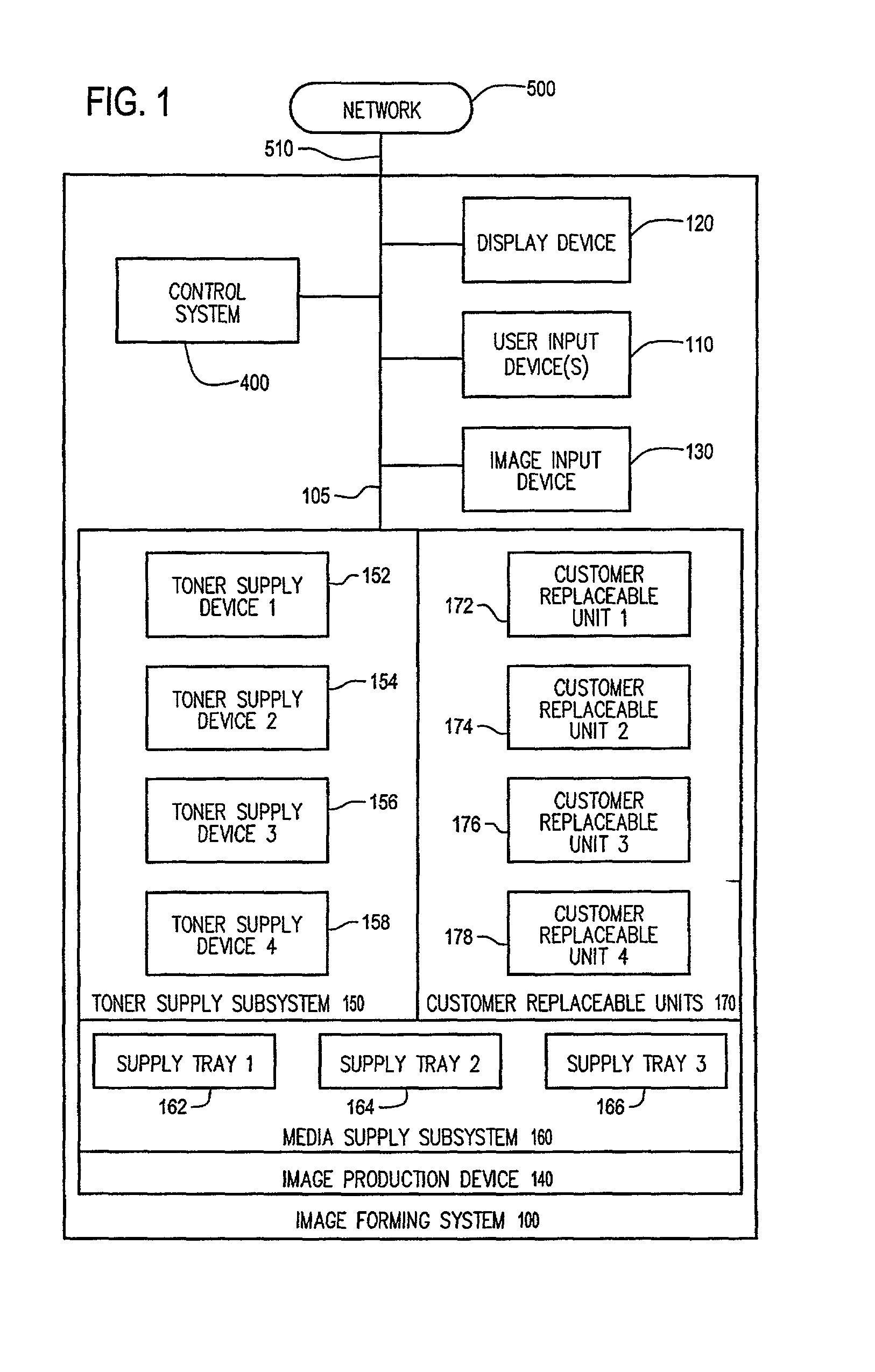
[0027]FIG. 1 shows an exemplary embodiment of an image forming system 100 according to the invention. As shown in FIG. 1, the image forming system 100 includes an image control system 400, one or more user input devices 110, a display device 120, an image input device 130, and an image production device 140. The image forming device 100 is also connected to a network 500 over a link 510. The image production device 140 contains a toner supply subsystem 150, a media supply subsystem 160 and a number of customer replaceable units 170. The toner supply subsystem 150 includes any desired number of individual toner supply devices, such as the first-fourth toner supply devices 152, 154, 156 and 158, respectively shown in FIG. 1. Each toner supply device 152–158 contains a limited amount of a distinct type (color, composition and / or the like) of toner that is gradually consumed as the image forming system 100 forms images on recording sheets according to various jobs. Each toner supply dev...


PUM


Abstract

Informing the user when consumables and / or customer replaceable units will have to be resupplied, changed and / or replaced, relative to the jobs sent to the image forming system, is a beneficial way to avoid unnecessary printing delays. When a job is added to a job queue or repositioned within the job queue, a warning can be associated with that job, and displayed to the user. With this information, the user can pre-emptively add a consumable and / or to replace a customer replaceable unit to avoid delays and maintain productivity. Alternatively, if such a system fault would occur prior to an urgent job reaching the top of the job queue, the user can manipulate the order and / or presence of the various jobs in the queue to ensure the high-priority job is completed before the consumable is fully exhausted and / or the customer replaceable unit reaches the end of its useful life.

Description

BACKGROUND OF THE INVENTION[0001]1. Field of Invention[0002]This invention is directed to an image forming system that has limited amounts of consumable materials and / or that uses customer replaceable units.[0003]2. Description of Related Art[0004]Printers, copiers and other types of image forming systems have become ubiquitous office productivity tools for generating tangible copies of original documents and / or electronic documents. Under normal circumstances, a user would send a print request to the image forming system and then retrieve the formed image.[0005]Invariably, problems arise when making copies on a recording medium. Problems such as lack of the recording media, depleted toner supplies, consumption of the useful life of customer replaceable units (CRU's), and / or malfunctions of the customer replaceable units due to old or broken parts, result in lower productivity and additional cost to the user and / or customer.[0006]The above-described problems that arise during image ...

Claims


Application Information

Patent Timeline
Patent Type & Authority Patents(United States)
IPC IPC(8): G06F13/00G06F15/00G03G21/00G03G15/00G06F3/12
CPCG03G15/556G03G15/553
Inventor WILLIS, KEITH L.MYERS, THOMAS
Owner XEROX CORP
Learn More