
Method and apparatus for using barrier phases to synchronize processes and components in a packet switching system

a packet switching and barrier phase technology, applied in data switching networks, frequency-division multiplexes, instruments, etc., can solve the problems of inability to achieve common timing strobes, and inability to use common timing strobes

Inactive Publication Date: 2006-03-07
CISCO TECH INC
View PDF33 Cites 18 Cited by
  • Summary
  • Abstract
  • Description
  • Claims
  • Application Information

AI Technical Summary

Benefits of technology

The patent describes a system and method for sending multiple sets of data in an ordered manner. When a barrier phase transition occurs, the system resets the current data set indicator to a predetermined ordered set. The data set indicator is then advanced to the next set of data. This allows for smooth and efficient transmission of multiple sets of data without interruption.

Problems solved by technology

In many of these configurations, a common timing strobe is infeasible.
However, a typical artifact of routing across multiple links of varying delays is the need to resequence each of the streams of packets routed through a packet switch back into their original order.
This technique is simple, but it requires significant resources for the buffers and sequence number counters.
This problem is further compounded when contiguous sequence numbers are not used or when a packet is lost or dropped.
In either of these cases, it is hard to determine whether certain packets should be forwarded immediately or should be delayed to see if a potentially dropped or lost packet or a packet with the skipped sequence number actually arrives.
This approach typically generates a large peak of messages at a time when the switching system is possibly already suffering from a lack of bandwidth in one or more locations within itself.
However, this autonomous approach can lead to congestion and delays.

Method used


Image

  • Method and apparatus for using barrier phases to synchronize processes and components in a packet switching system
  • Method and apparatus for using barrier phases to synchronize processes and components in a packet switching system
  • Method and apparatus for using barrier phases to synchronize processes and components in a packet switching system

Examples


Embodiment Construction

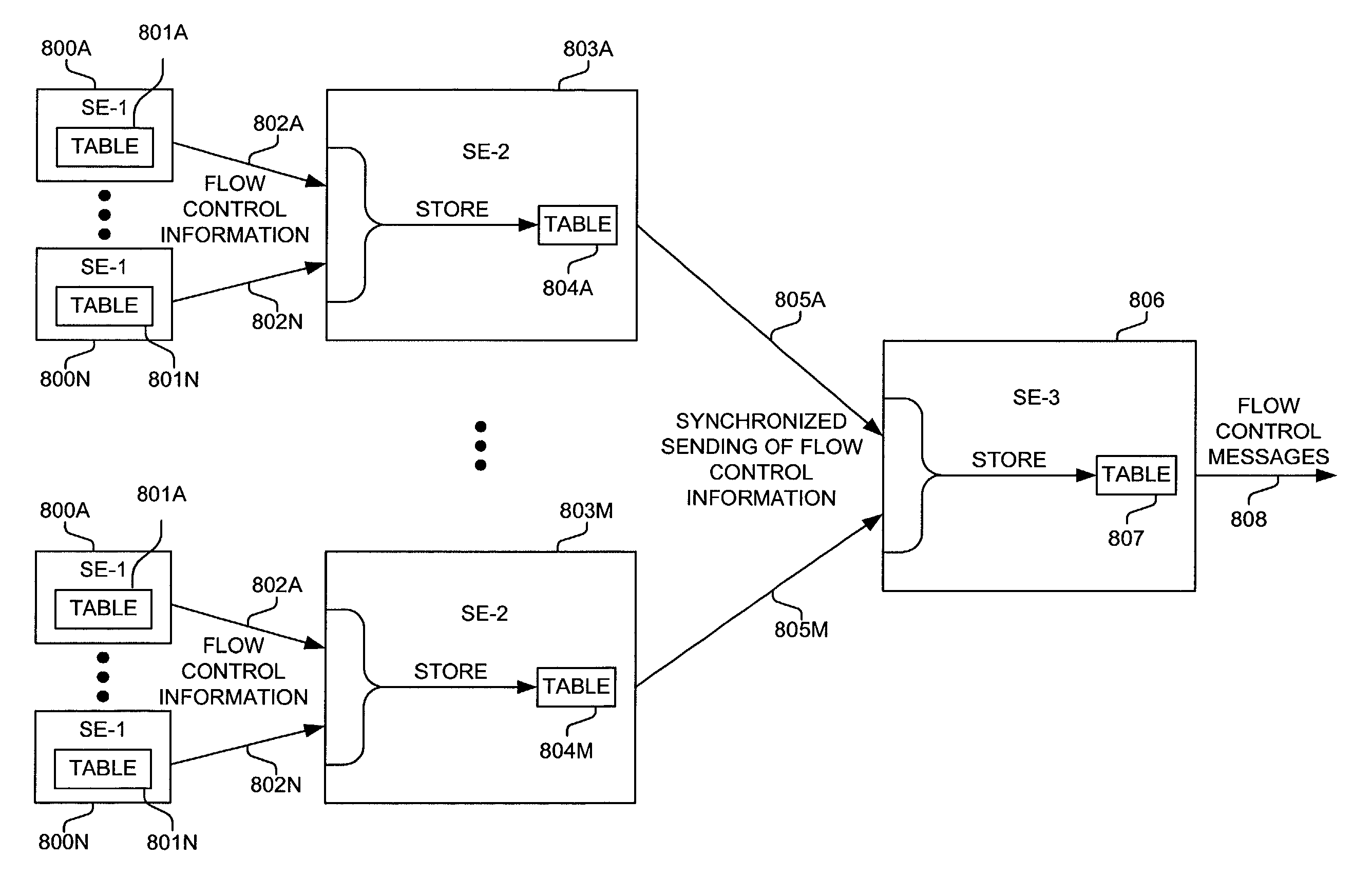
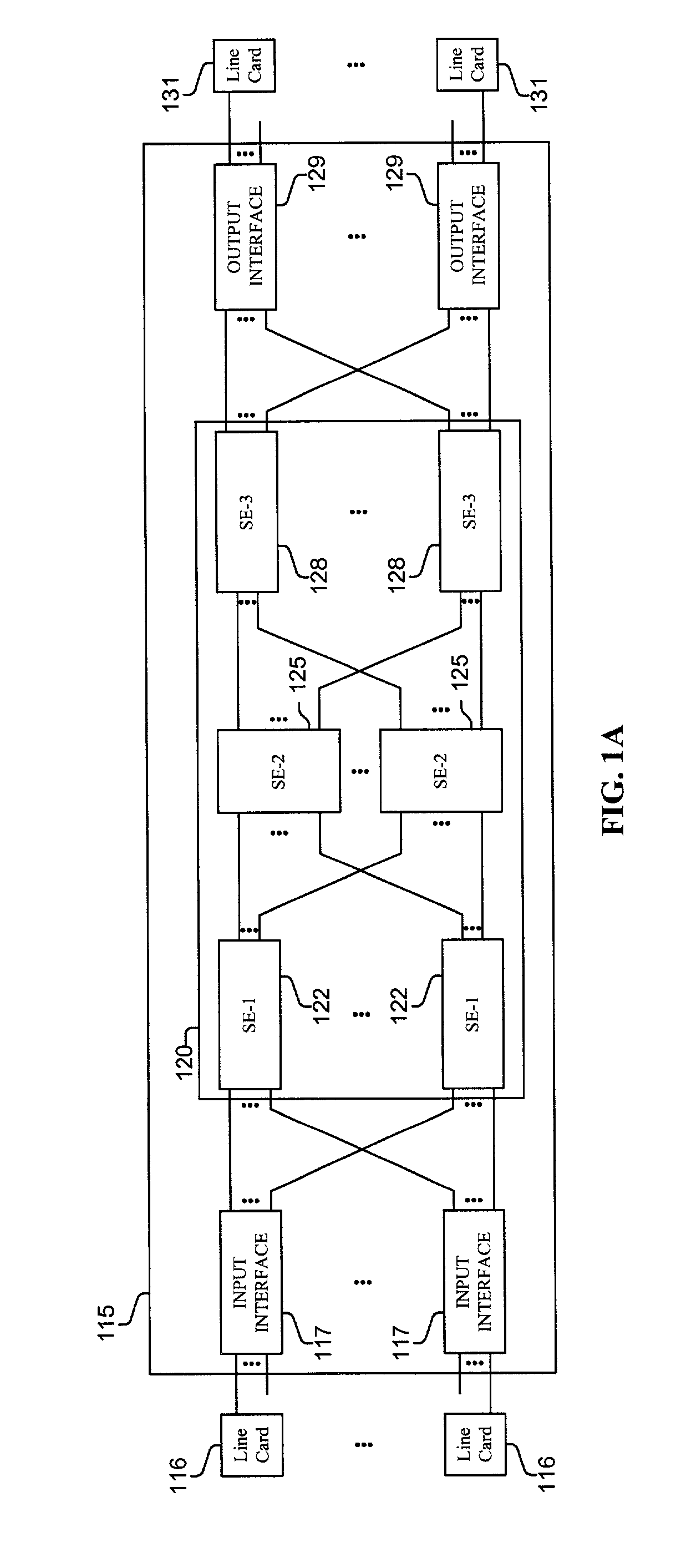
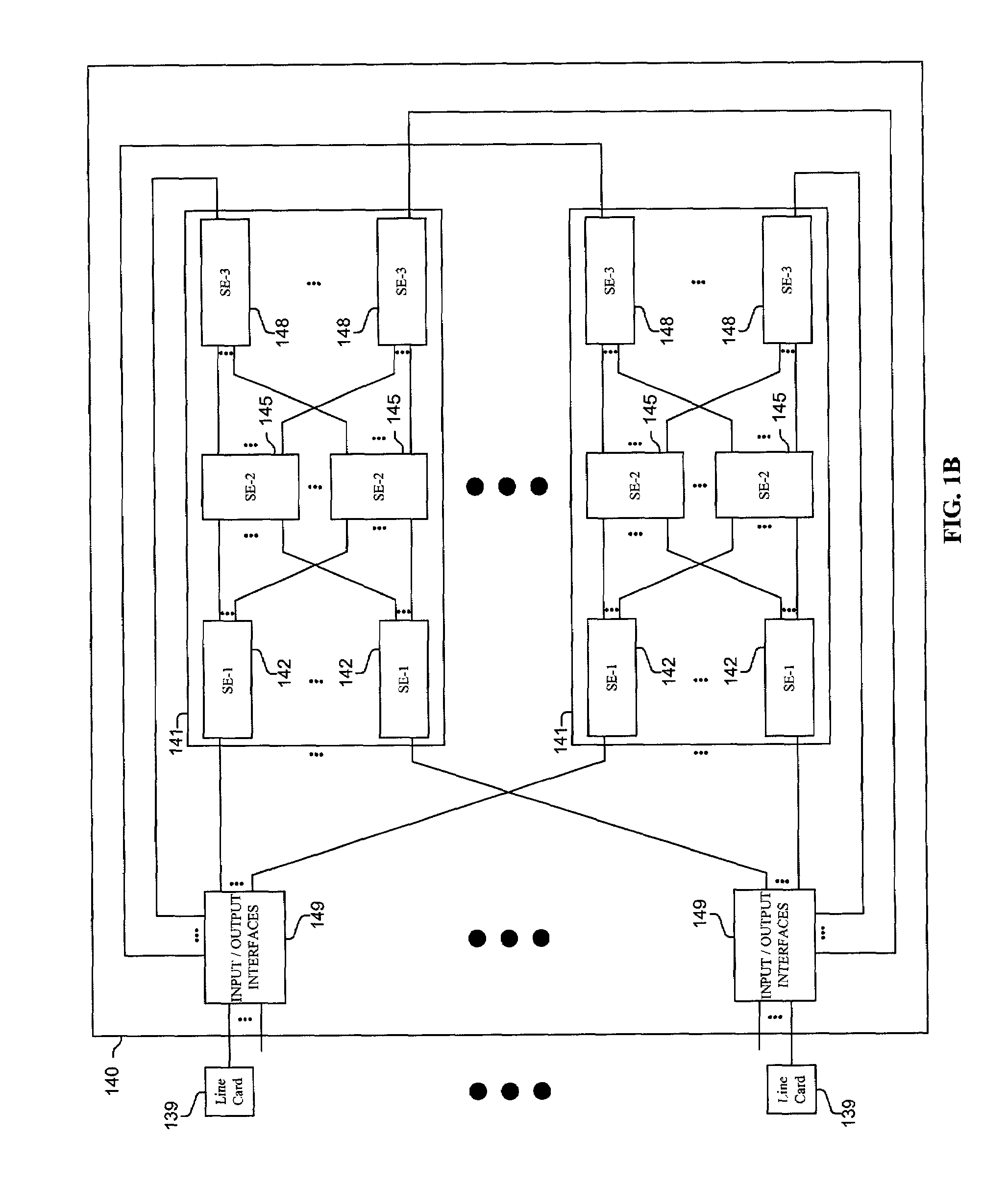
[0028]Methods and apparatus are disclosed for using barrier phases to synchronize processes and components in a packet switching system, including, for example, but not limited to the use of barrier phases in the coordinated timing of the sending of information within a packet switching system, and the use of barrier phases in a packet sequence number windowing protocol. The use of barrier phases may be used in most any device or system for example, inter alia, in a computer or communications system, such as a packet switching system, router, or other device.

[0029]The methods and apparatus disclosed herein are not limited to a single computer or communications system. Rather, the architecture and functionality taught herein are extensible to an unlimited number of computer and communications systems, devices and embodiments in keeping with the scope and spirit of the invention. Embodiments described herein include various elements and limitations, with no one element or limitation c...


PUM


Abstract

Methods and apparatus are disclosed for using barrier phases to synchronize processes and components in a packet switching system, including, for example, but not limited to the use of barrier phases in the coordinated timing of the sending of information (e.g., flow control information) within a packet switching system, and the use of barrier phases in a packet sequence number windowing protocol. In one implementation, elements are assigned to one of multiple ordered sets of a barrier groups, wherein each element of a barrier group must be set to a common barrier state before any element of a next a barrier group can switch to a next barrier state, and once all elements of a particular barrier group switch to a new barrier state, all the elements of the next barrier group begin to switch to the next barrier state.

Description

CROSS-REFERENCE TO RELATED APPLICATIONS[0001]This is a continuation-in-part of copending nonprovisional application Ser. No. 09 / 752,422, filed Dec. 31, 2000, which is hereby incorporated by reference.FIELD OF THE INVENTION[0002]This invention relates to a packet switching system of communications systems, routers, computers and communications devices; and more particularly, the invention relates to using barrier phases to synchronize processes and components in a packet switching system, including, for example, but not limited to the use of barrier phases in the coordinated timing of the sending of information within a packet switching system, and the use of barrier phases in a packet sequence number windowing protocol.BACKGROUND OF THE INVENTION[0003]The communications industry is rapidly changing to adjust to emerging technologies and ever increasing customer demand. This customer demand for new applications and increased performance of existing applications is driving communicati...

Claims


Application Information

Patent Timeline
Patent Type & Authority Patents(United States)
IPC IPC(8): H04L12/56H04L12/00
CPCH04L47/10H04L47/24H04L47/26H04L49/9094H04L47/34H04L49/1523H04L49/90H04L47/33
Inventor MICHELSON, JONATHAN E.WILLIAMS, JR., JOHN J.DEJANOVIC, THOMASFINGERHUT, JOHN ANDREW
Owner CISCO TECH INC
Learn More