Autognomic decision making system and method

a decision-making system and autognomic technology, applied in the field of autognomic decision-making system and method, can solve the problems of limited system and computational complexity of the system

Inactive Publication Date: 2003-01-07
UNISYS CORP
View PDF1 Cites 45 Cited by
  • Summary
  • Abstract
  • Description
  • Claims
  • Application Information

AI Technical Summary

Problems solved by technology

However, such systems are limited by the models used to create them.
However, such systems have been computationally complex.

Method used


Image

  • Autognomic decision making system and method
  • Autognomic decision making system and method
  • Autognomic decision making system and method

Examples


Embodiment Construction

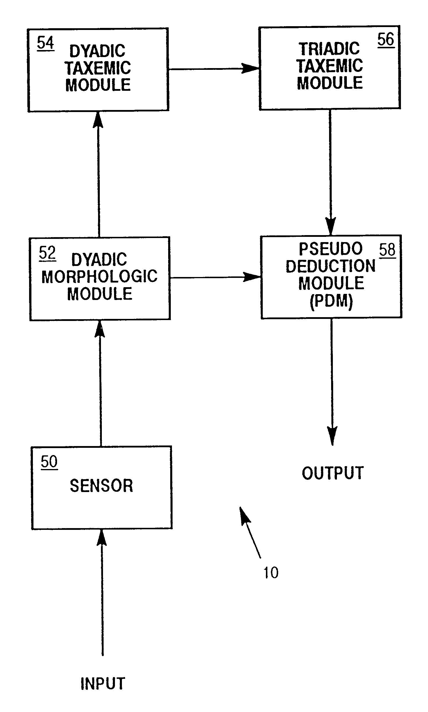
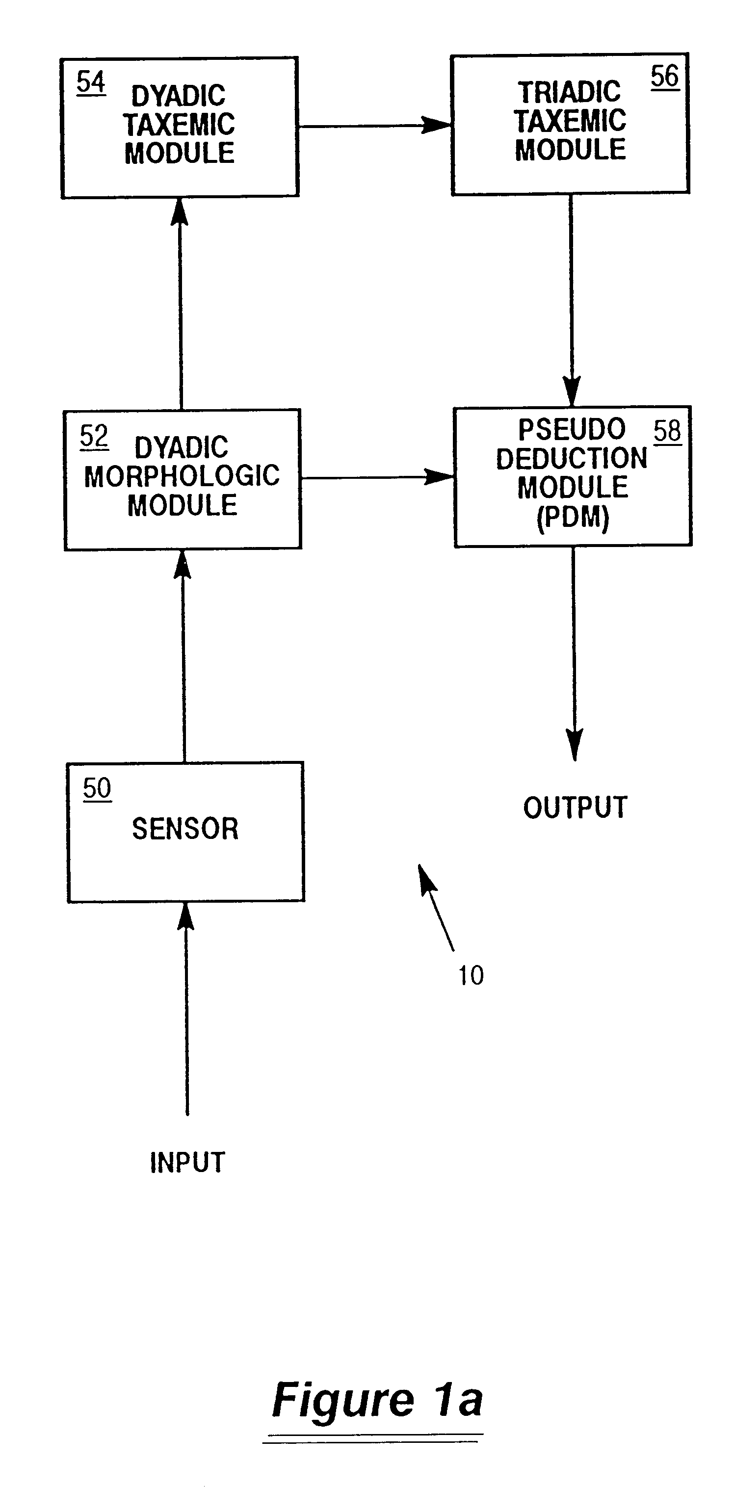
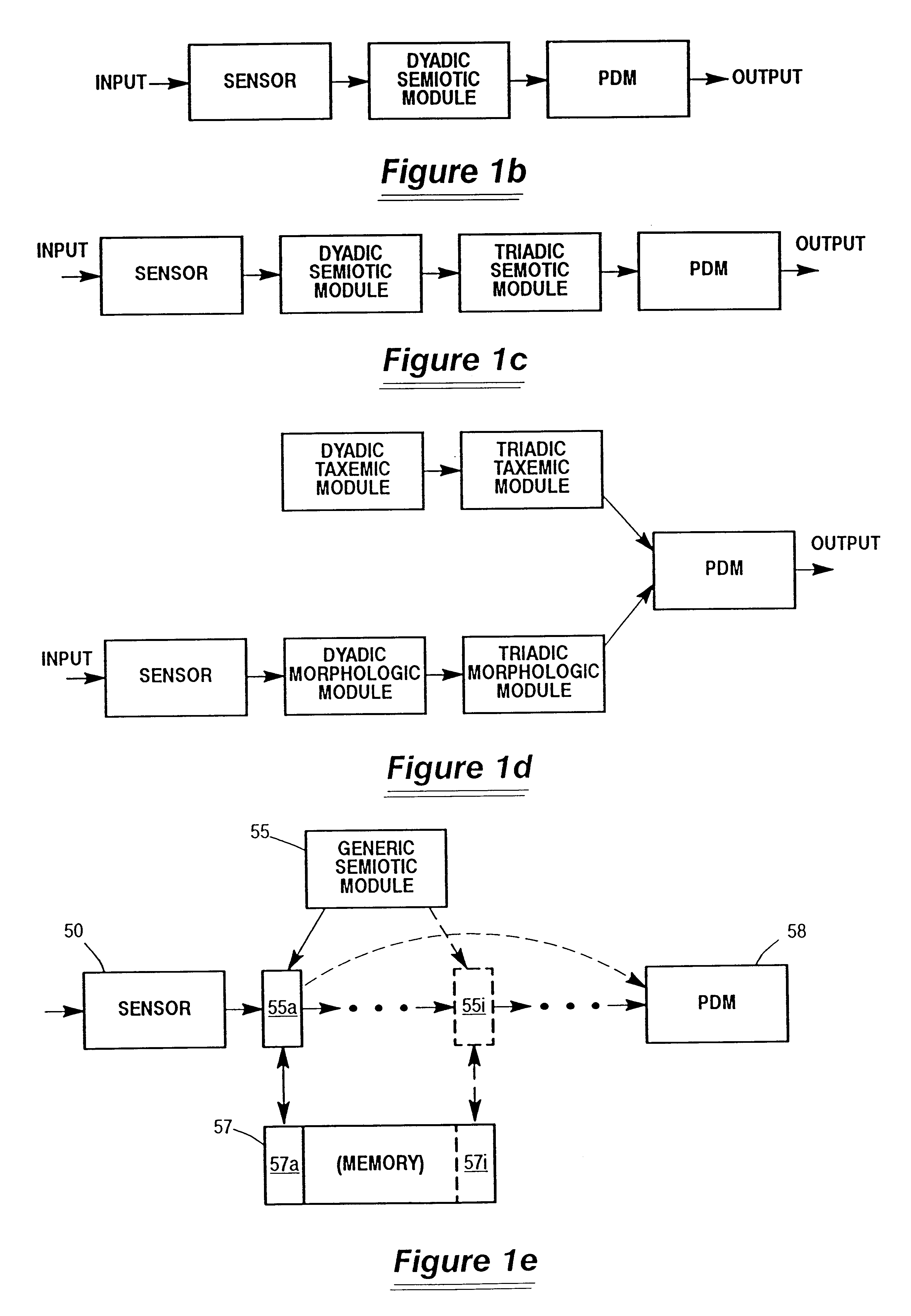
FIG. 1a shows the five major components of a gnome 10 of a presently preferred embodiment. The gnome 10 has a sensing module 50, a dyadic morphologic module 52, a dyadic taxemic module 54, a triadic taxemic module 56 and a pseudo deduction module 58. The dyadic and triadic modules 52, 54, 56 all utilize semiotic processing and are also referred to as semiotic modules.

The sensor 50 acts as the interface between the other components in the gnome and the training and query data which it senses. The sensor 50 is configured to receive data in a prespecified format and identifies elemental symbols to be analyzed and, preferably, identifies or creates two orders of delimiters. The first order delimiters identify first order sets of sequential elemental symbols; the second order delimiters identify second order sets of sequential first order sets.

In the preferred embodiment, text is sensed by the sensor 50. Alpha-numeric characters are identified as elemental symbols. Spaces and punctuation...


PUM


Abstract

A sensor module is for use in a semiotic processing system. The sensing module receives data in a pre-specified format. It identifies sequential elemental symbols in the received data. First order sets of identified sequential element symbols are defined such that no first order set has more than a maximum number of sequential elemental symbols. Second order sets of sequential first order sets are defined such that no second order set has more than a maximum number N of sequential first order sets.

Description

1. Field of the InventionThe invention generally relates to a method and system for making decisions based on a statistical interpretation of sign or symbol relationships. In particular, the invention relates to a method and system for making decisions based on a recursive statistical interpretation of linguistic sign and symbol relationships.2. Description of the Prior ArtThere have been a variety of approaches taken in developing devices which can interpret linguistic information. One known approach is to create a model of language by defining rules of grammar that are used by the system. In such systems, concepts such as nouns and verbs must be codified in software or by some other means for the system to have understanding of the human language. One advantage of such a system is that the knowledge of the designers is provided through code to the system. However, such systems are limited by the models used to create them.Another approach is to allow a device itself to interpret t...

Claims


Application Information

Patent Timeline
Patent Type & Authority Patents(United States)
IPC IPC(8): G06F15/18G06N5/045
CPCG06N99/005G06N20/00G06N5/045
Inventor REED, FREDERICK W.PARKER, CHARLES AUSTIN
Owner UNISYS CORP
Why Eureka
Try Eureka